the Creative Commons Attribution 4.0 License.
the Creative Commons Attribution 4.0 License.
 | 06 Sep 2019
Low-noise permalloy ring cores for fluxgate magnetometers
Miroslaw Ciurzynski
David Barona
B. Barry Narod
John R. Bennest
Andy Kale
Marc Lessard
David K. Milling
Joshua Larson
Ian R. Mann
Fluxgate magnetometers are important tools for geophysics and space physics, providing high-precision magnetic field measurements. Fluxgate magnetometer noise performance is typically limited by a ferromagnetic element that is periodically forced into magnetic saturation to modulate, or gate, the local magnetic field. The parameters that control the intrinsic magnetic noise of the ferromagnetic element remain poorly understood. Much of the basic research into producing low-noise fluxgate sensors was completed in the 1960s for military purposes and was never publicly released. Many modern fluxgates depend on legacy Infinetics S1000 ring cores that have been out of production since 1996 and for which there is no published manufacturing process. We present a manufacturing approach that can consistently produce fluxgate ring cores with a noise of ∼6–11 pT per square root hertz – comparable to many of the legacy Infinetics ring cores used worldwide today. As a result, we demonstrate that we have developed the capacity to produce the low-noise ring cores essential for high-quality, science-grade fluxgate instrumentation. This work has also revealed potential avenues for further improving performance, and further research into low-noise magnetic materials and fluxgate magnetometer sensors is underway.


Fluxgate magnetometers (e.g., Primdahl, 1979) are important tools for geophysics, solar–terrestrial and space physics, space exploration, and monitoring space weather. They provide high-precision measurements of Earth's magnetic field that can be used to image downward into the Earth, resolving subsurface conductivity via magnetotellurics, and upward into near-Earth space, inferring the currents and waves coupling the ionosphere to the magnetosphere. Fluxgate magnetometers deliver a magnetic field measurement by modulating (gating) the local magnetic field by periodically saturating a piece of ferromagnetic core material – often in the form of a ring (Fig. 1). The ferromagnetic core alone would act as a magnetic-flux concentrator, but combined with a toroidal drive winding to periodically drive it into magnetic saturation it acts as a magnetic-flux modulator – or a fluxgate. The addition of a solenoidal sense winding completes the fluxgate sensor as the, now modulated, magnetic field induces a current or voltage that can be conditioned and digitized.
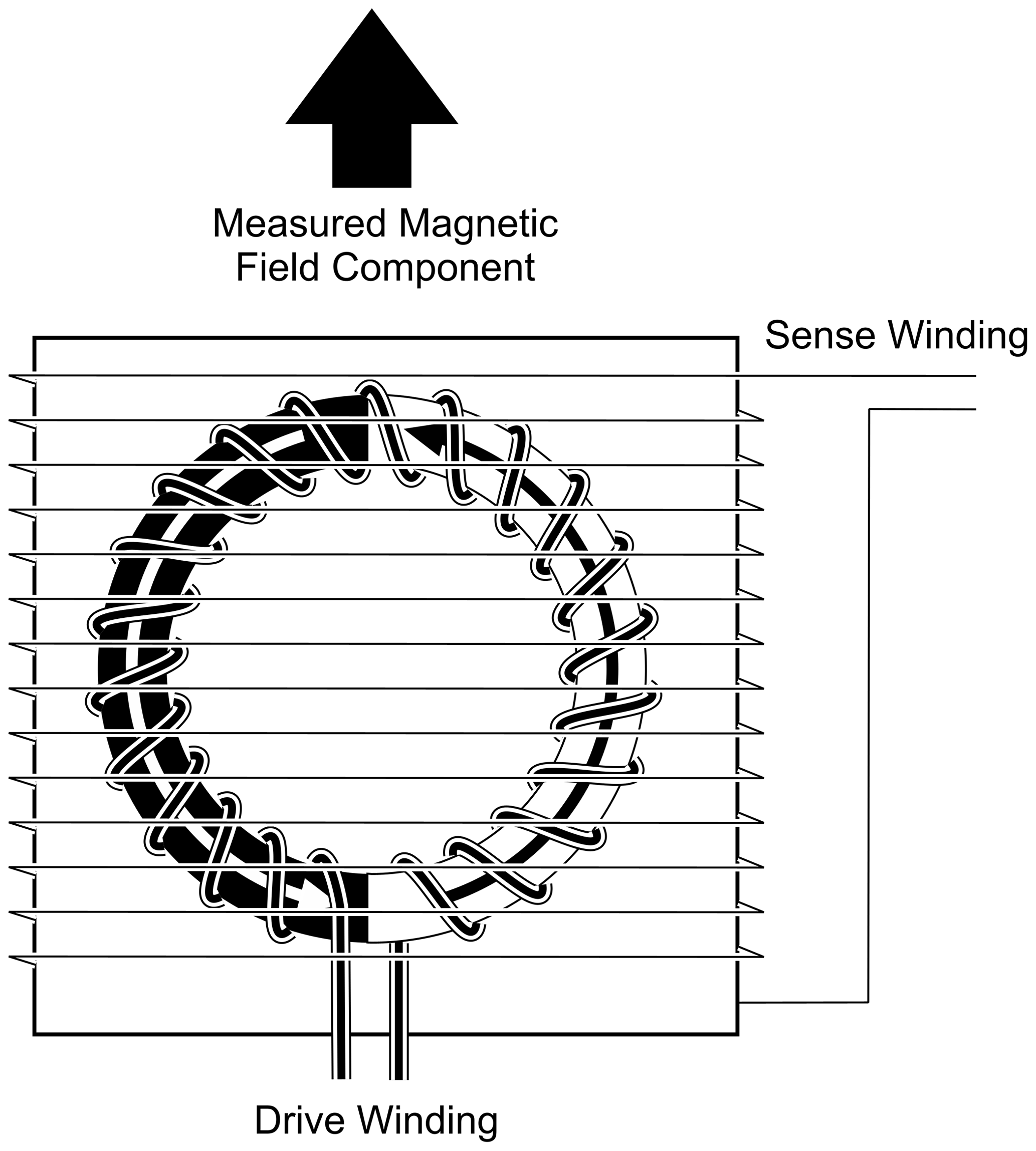
Figure 1A fluxgate sensor has three primary components: a ferromagnetic core, a drive winding to periodically force the ferromagnetic core into magnetic saturation, and a sense winding to pick up the modulated (gated) field. Reproduced from Miles et al. (2017).
The instrumental noise floor of the sensor is typically limited by the intrinsic magnetic noise of the ring core as it is driven in and out of magnetic saturation. Despite their widespread use, the parameters that control the limiting intrinsic magnetic noise of a fluxgate ring core remain poorly understood. The key research and manufacturing process for low-noise fluxgate ring cores are insufficiently documented (Narod, 2014) for comparable ring cores to be reproduced. Here we document a ring-core manufacturing process that has been developed from the limited historical documentation that exists, much of which dates to the 1960s. This process yields fluxgate ring cores comparable to those produced historically and serves as a baseline for further low-noise fluxgate ring-core development.
1.1 History of 6-81 permalloy
A preferred ferromagnetic material used in fluxgate sensors is 6-81 permalloy containing 6 % molybdenum, 81.3 % nickel, and the remainder iron. The 6-81 permalloy is visible in the ring core in Fig. 2 as the glossy grey metal within the black supporting bobbin. The earliest known reference to 6-81 permalloy is by Odani (1964), who examined magnetic properties for 5.3 %–6.8 % molybdenum permalloy processed into thin foils and heat-treated. Pfeifer (1966) undertook similar but wider-ranging work that was introduced to the English language literature by English and Chin (1967). Pfeifer and Boll (1969) explored the magnetic properties of similar alloys for applications such as transformers and magnetic amplifiers. The US Naval Ordinance Laboratory was aware of the utility of 6-81 permalloy as early at 1965 (Scanlon, 1966); however, few details of their research are available to the public.
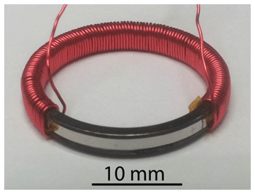
Figure 2An S1000-compatible fluxgate ring core. The red enameled wire forming the drive winding has been partially removed for the photograph, exposing the ferromagnetic sense element (silver) and the supporting bobbin (black).
A. W. Geyger (1962) and W. A. Geyger (1962) suggested the use of thin foils as a way to suppress eddy currents when constructing fluxgate magnetometers. However, it seems unlikely that, at the time, the researchers understood how the choice of foil thickness was impacting parameters such as grain size that appear to have controlled the magnetic noise of the sensors they were constructing (e.g., later work by Pfeifer and Kunz, 1977; Pfeifer and Radeloff, 1980). The potential of 6-81 permalloy to be used in magnetic field instruments was established in a seminal work by Gordon et al. (1968). Two other groups are known to have constructed fluxgate sensors from 6-81 permalloy. The Themis (Auster et al., 2008) ring cores result from years of research in Germany (Müller et al., 1998) and achieved noise better than 5 pT Hz using a 20 µm foil. Musmann (2010) describe similar noise performance and also used a 20 µm foil.
It is noteworthy that none of the works of this era published sufficient details for their process to be understood unambiguously. Much subsequent work has involved rediscovering the manufacturing details that controlled parameters such as homogenization and recrystallization. To fully understand these materials, it may be necessary to document the complete manufacturing history from melt to final heat treatment. The approach to sensor construction presented here is based on this historical research and attempts to develop a process that can produce comparable results.
1.2 The S1000 ring core
Somewhat remarkably, virtually all the permalloy used in North American fluxgate magnetometers appears to have been manufactured from a single batch of 6-81 permalloy, likely by the Hamilton Watch Company, in or around 1969. This permalloy was then rolled into 12 and 3 µm thick foils and was subsequently processed to engineer low magnetic noise by two groups – the US Naval Surface Weapons Center (NSWC) White Oak (now a Department of Agriculture facility) and Infinetics Inc. (Scarzello et al., 2001). Many modern fluxgates depend on legacy Infinetics S1000 ring cores that have been out of production since 1996. Infinetics ring cores are in use in terrestrial applications such as the US EarthScope (Schultz, 2009), the Canadian NRCan magnetic observatory array (Danskin et al., 2009), and the Geospace Observatory (GO) Canada CARISMA magnetometer array (Mann et al., 2008); they are also used on space missions including the US MAGSAT sensor (Acuña et al., 1978), the UK Double Star fluxgate sensor (Carr et al., 2005), and the Canadian e-POP MGF sensor (Wallis et al., 2015).
In some cases, the providence of the ring cores is complicated and difficult to know for certain. For example, the outboard sensor on Double Star was manufactured by Ultra Electronics (Carr et al., 2005), the inboard sensor having been developed at the Technical University in Braunschweig, Germany (Auster et al., 2008; Fornacon et al., 1999). However, there is significant, albeit circumstantial, evidence that the Ultra Electronics sensor was manufactured from Infinetics S1000 ring cores. Around 1993 there was a management buyout at Ultra Electronics that appears to have included Domain Magnetics–Dowty Aerospace, who are known to have held a significant stock of Infinetics ring cores. The Double Star sensor has comparable geometry to the Cassiope–e-POP (Wallis et al., 2015) sensor, suggesting that its ring cores are at least geometrically similar to the Infinetics S1000. Ultra Electronics sensors also have similar noise performance of <7 pT Hz at 1 Hz (Carr et al., 2007; Kellock et al., 1996). Finally, Ultra Electronics has stated that the ring cores were manufactured in the USA (Christopher M. Carr, personal communication, 2013).
From this historical context, it becomes apparent why many magnetometers in use worldwide have nearly identical sensors (see Fig. 3); they all appear to be using legacy Infinetics S1000 ring cores. For this reason, the ring cores developed under this project were designed to be compatible with the S1000 form factor.
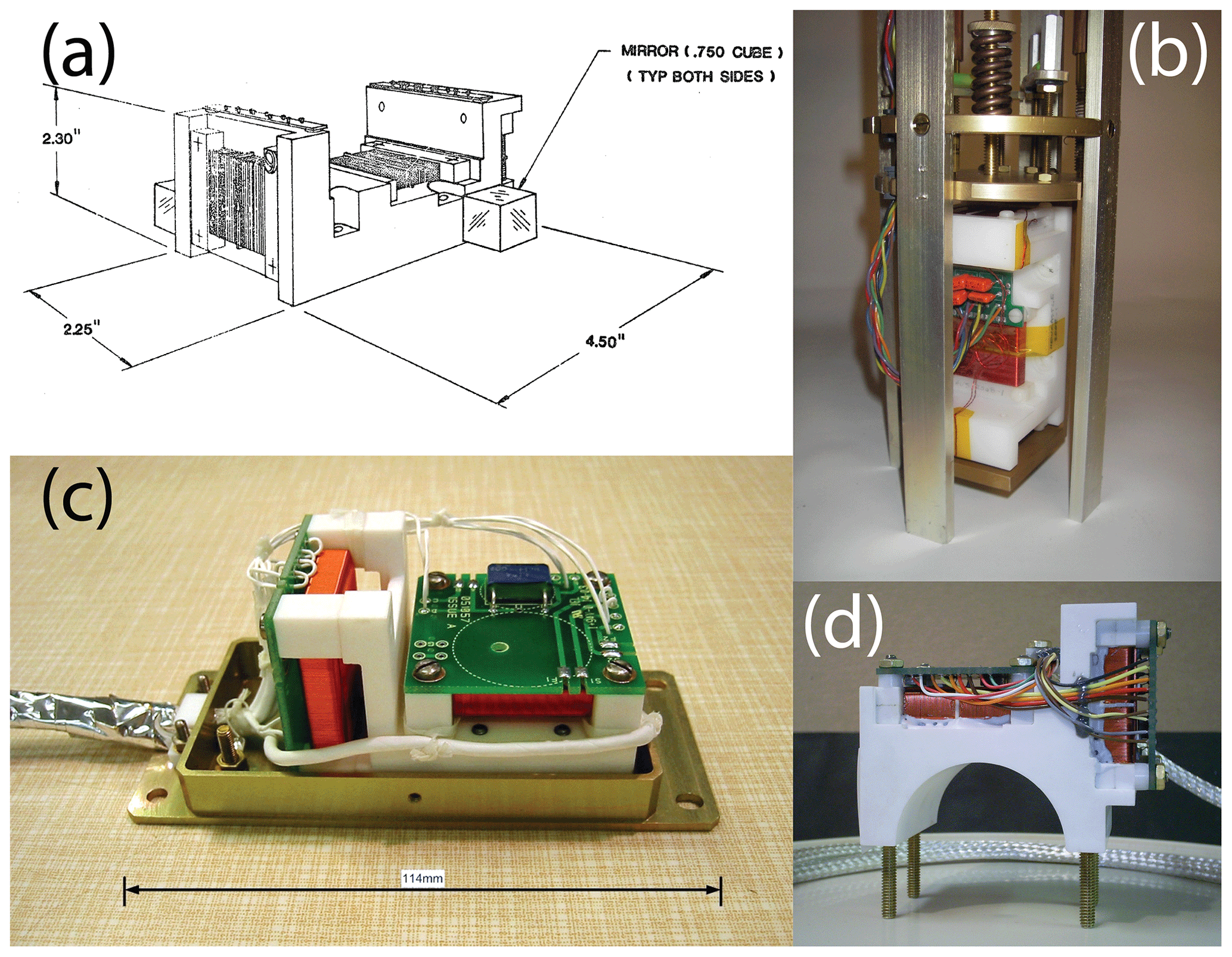
Figure 3Example fluxgate sensors believed to be based on the Infinetics S1000 ring core. (a) US MAGSAT sensor (image reproduced from Acuña et al., 1978), (b) Terrestrial NIMS magnetometer used in the NSF EarthScope project (Narod and Bennest, 1990), (c) the UK Double Star fluxgate sensor (image reproduced from Carr et al., 2005), and (d) the Canadian e-POP MGF sensor (image reproduced from Wallis et al., 2015).
The physical construction of the fluxgate ring core consisted of several steps illustrated in Fig. 4. A circular bobbin (a) established the geometry of the ring core and provided mechanical strength. The ferromagnetic element, used to modulate the magnetic field in the sensor, was constructed by spiral winding a thin strip of cold-rolled permalloy foil coated with an insulator (b). The assembled bobbin and strips were heat-treated in a reducing atmosphere to optimize their magnetic properties (c). The ring core was then electrically isolated using polyimide tape (d) and a toroidal drive winding was applied (e).
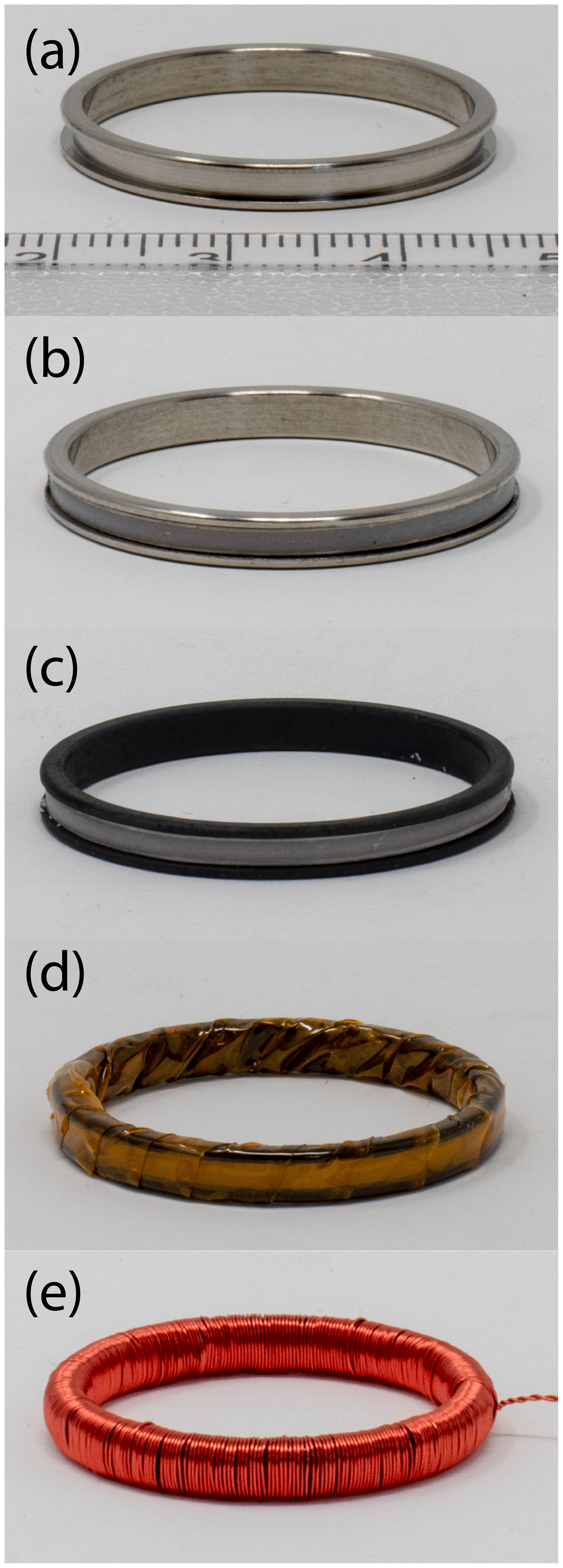
Figure 4Major steps in the production of an S1000-compatible ring core. (a) Inconel bobbin used to form the ring core and provide mechanical support. (b) Insulator-coated permalloy foil strips spiral-wound and welded to bobbin. (c) Same, but after heat treatment. (d) Wrapped in polyimide tape. (e) Drive winding applied.
2.1 Ring core bobbin
The bobbins in the ring cores described here had the geometry of the common S1000 bobbin, whose dimensions are shown in Fig. 5. The bobbin defined the geometry of the ring core and provided mechanical support to prevent the permalloy from experiencing mechanical strain after heat treatment. Even minor deformations or stresses applied to the ferromagnetic element, such as when pushing on the ring core to turn it within the sense winding, were found to significantly increase magnetic noise. The ferromagnetic element was spiral-wound into a groove machined into the outer circumference of the bobbin. This allowed a toroidal drive winding to be subsequently wound onto the bobbin without contacting or imparting stress onto the permalloy strip.
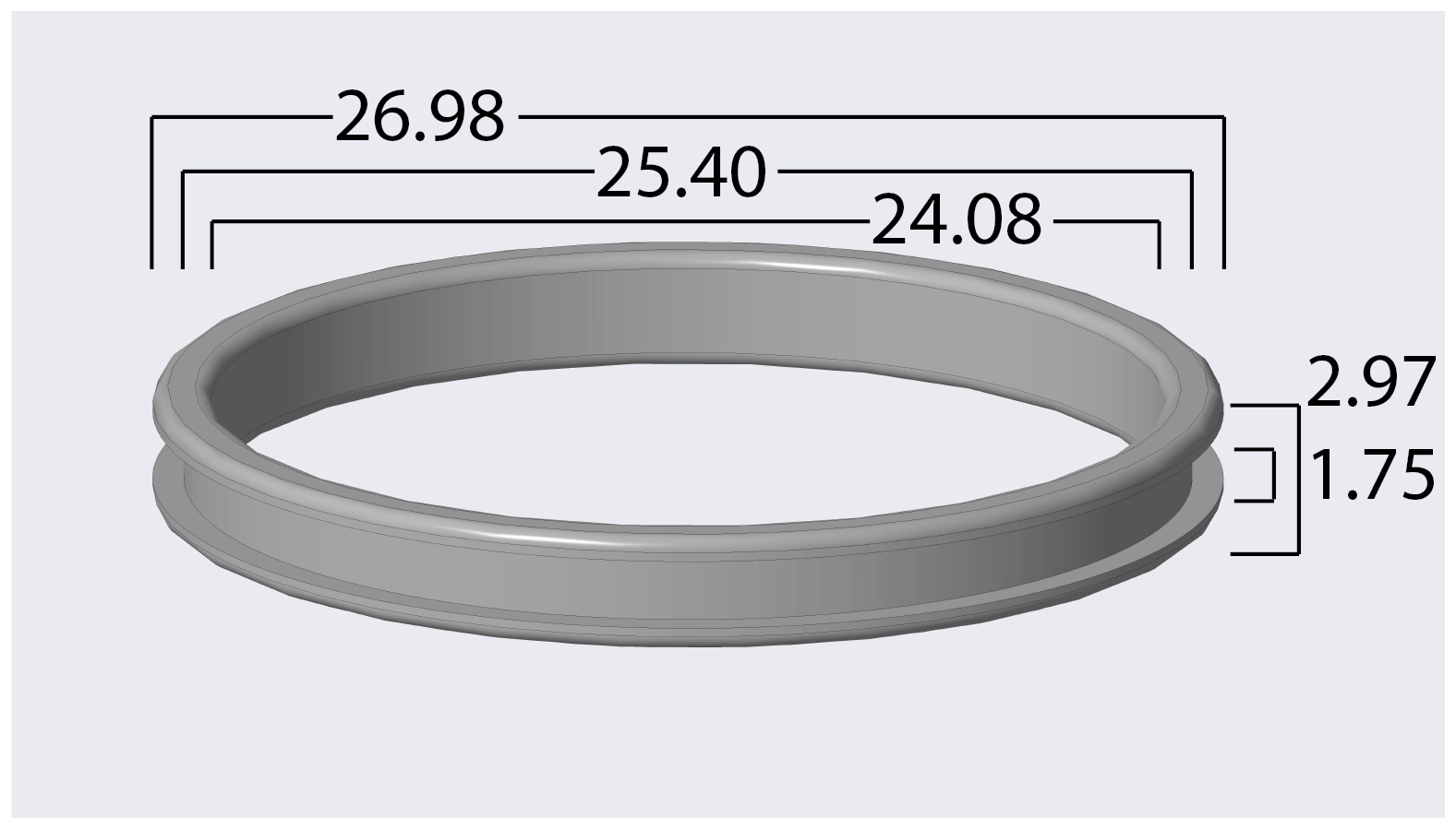
The bobbins were manufactured from Inconel x750 that was selected as being nonmagnetic and providing high rigidity even at the elevated temperatures of the heat treatment required to optimize the magnetic properties of the ring core. However, Inconel x750 was an imperfect match to the permalloy sense element in terms of linear thermal expansion (12.6 ppm ∘C−1 for Inconel x750 and estimated to be about 11.6 ppm ∘C−1 for 6-81 permalloy). Properties for the Inconel x750 were taken from the Special Metals Group of Companies data sheet, Unified Numbering System for Metals and Alloys, reference UNS N07750. The immediate impact of the thermal mismatch was differential expansion during the heat treatment, leading to a loose fit of the permalloy strip on the bobbin in the final ring-core assembly. The differential expansion may have also enhanced the magnetic noise by introducing mechanical stress during the heat treatment and if the final ring-core assembly was operated over a wide temperature range. This effect has not yet been investigated in detail. For future designs, alternative bobbin materials that are a closer thermal match are being explored. Potential candidates include Haynes alloy B3 and the nonmagnetic NiMo+X alloy class suggested by Musmann (2010) and potentially referenced by Afanassiev et al. (1980). Both have low chromium content, which is desirable as the chromium becomes volatile when heat-treated at higher temperatures.
2.2 Manufacturing thin 6-81 permalloy foil
A custom 4 kg ingot of 6-81 permalloy was created at the Canadian government CANMET lab. Following the suggestion of CANMET staff, a vacuum arc furnace was used to create a 50–50 alloy of molybdenum and nickel and then melting in the remaining constituents in a conventional furnace. Subsequent work has shown that it is possible to dissolve molybdenum into nickel at ∼1450 ∘C, providing a simple method to manufacture small quantities of 6-81 permalloy in a laboratory setting. Some 6-81 alloys are now available from commercial sources (e.g., SUPERMIMPHY LLS manufactured by Aperame). However, minimum purchase requirements (often ∼100 kg) can make commercial procurement expensive for small-quantity development. Custom manufacturing of the 6-81 alloy also ensures that its heat-treatment history, which controls both grain development and homogeneity, is well documented.
The complete alloy was intended to be reduced by hot rolling. However, the process was stopped almost immediately as the alloy began to develop severe surface cracking (Fig. 6). This may have resulted from partial melting near the surface due to inhomogeneity in the mix or the alloy being non-eutectic. The cooled ingot was instead machined into 3 mm thick stock using a milling machine. The 3 mm stock was then heat-treated at 1100 ∘C in a 5 % hydrogen atmosphere for 7 d to homogenize the material before further processing.
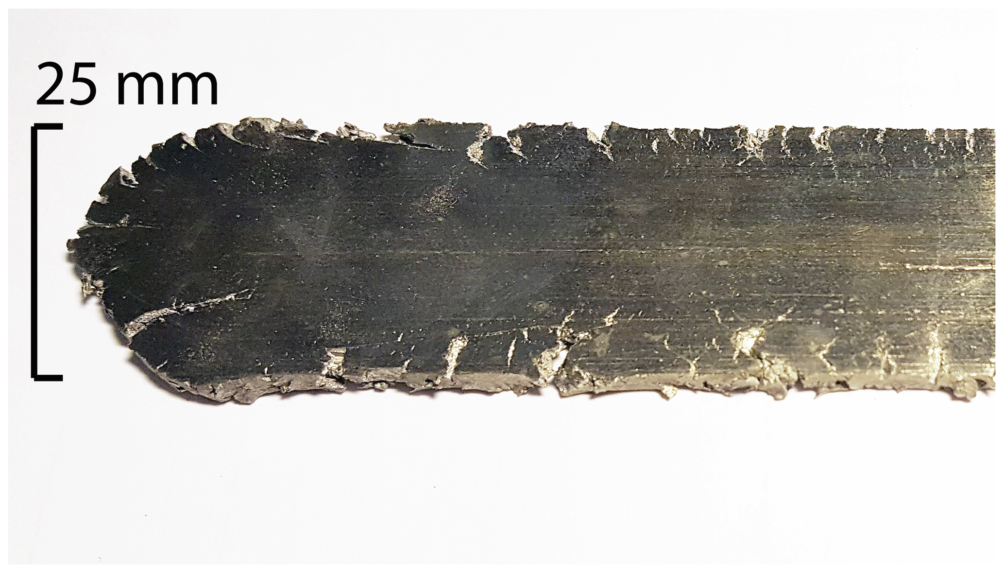
Figure 6A 3 mm thick stock machined from the 6-81 permalloy ingot showing the surface cracking that resulted from an attempt at hot rolling.
Successive cold rolling reduced the permalloy from 3 mm to the final foil thickness of ∼100 µm in the ring cores presented here. Cold rolling was intended to lock mechanical strain into the permalloy that the authors speculate serves as a free energy source to drive crystal grain growth during the final heat treatment, in a process now referred to as primary recrystallization (Pfeifer and Radeloff, 1980). For this reason, no interim heat treatments to soften the material were performed during the cold rolling. The material became harder as it was thinned and strained during each cold roll (work hardening), requiring many small passes with each accomplishing a reduction of less than ∼5 % of the thickness. The hardness of the cold-rolled permalloy and the desired thickness (≤100 µm) placed significant requirements on the rolling mill. Deformation of the rollers and/or compression of the bearings created a practical limit of ∼100 µm for the current rolling configuration.
The thinnest results to date were achieved using a Cavallin bench rolling mill for plate–strip model L.80/44-044 adapted with a reducing gear and a 735 W electric motor. The 44 mm diameter rollers and solid bronze bushings allow more force to be applied to the foil than other, nominally comparable, rolling mills. The current rolling mill setup (Fig. 7a) reduced 3 mm permalloy stock (Fig. 7b) to 100 µm foil (Fig. 7c) in approximately 250 passes. Subsequent passes provided no further significant reductions in the foil thickness.
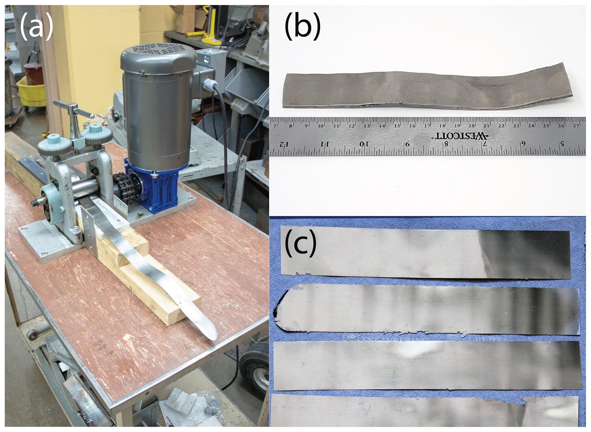
Figure 7(a) Modified Cavallin rolling mill used to reduce the permalloy foil. (b) A 3 mm thick slice of a custom 6-81 permalloy ingot. (c) Cold-rolled 100 µm thick foil.
The permalloy was then cut into 1.57 mm wide strips to fit within the groove cut into the external face of the bobbin used in S1000 form factor ring cores (see Fig. 5). The cold-rolled permalloy, despite work hardening, remained sufficiently ductile that it tended to fold rather than cut. A sharp guillotine shear could cut the permalloy foil if supported by a sacrificial brass sheet, but electro-discharge machining (EDM) and water jetting, while requiring more expensive infrastructure, were found to provide superior cutting results.
The permalloy strips were coated with magnesium oxide (an electrical insulator) to prevent the formation of spot-welds between layers when the strip was attached by electrical discharge welding and to prevent the tightly wound layers from fusing with each other during heat treatments. This insulator was created using an established process (Bill Billingsley Sr., personal communication, 2008) from milk of magnesia, Mg(OH)2, diluted with water to reduce its viscosity and form a consistent thin layer. The strip was dipped, hung up, and allowed to air-dry (Fig. 8a). During the heat treatment the milk of magnesia residue (Fig. 8b) formed a thin but robust layer of magnesium oxide, MgO, that electrically isolates each layer and minimizes eddy currents. Other capable insulating coatings and application methods are possible, as described by Musmann (2010), the main requirement being that they can survive the heat treatment in a hydrogen atmosphere.
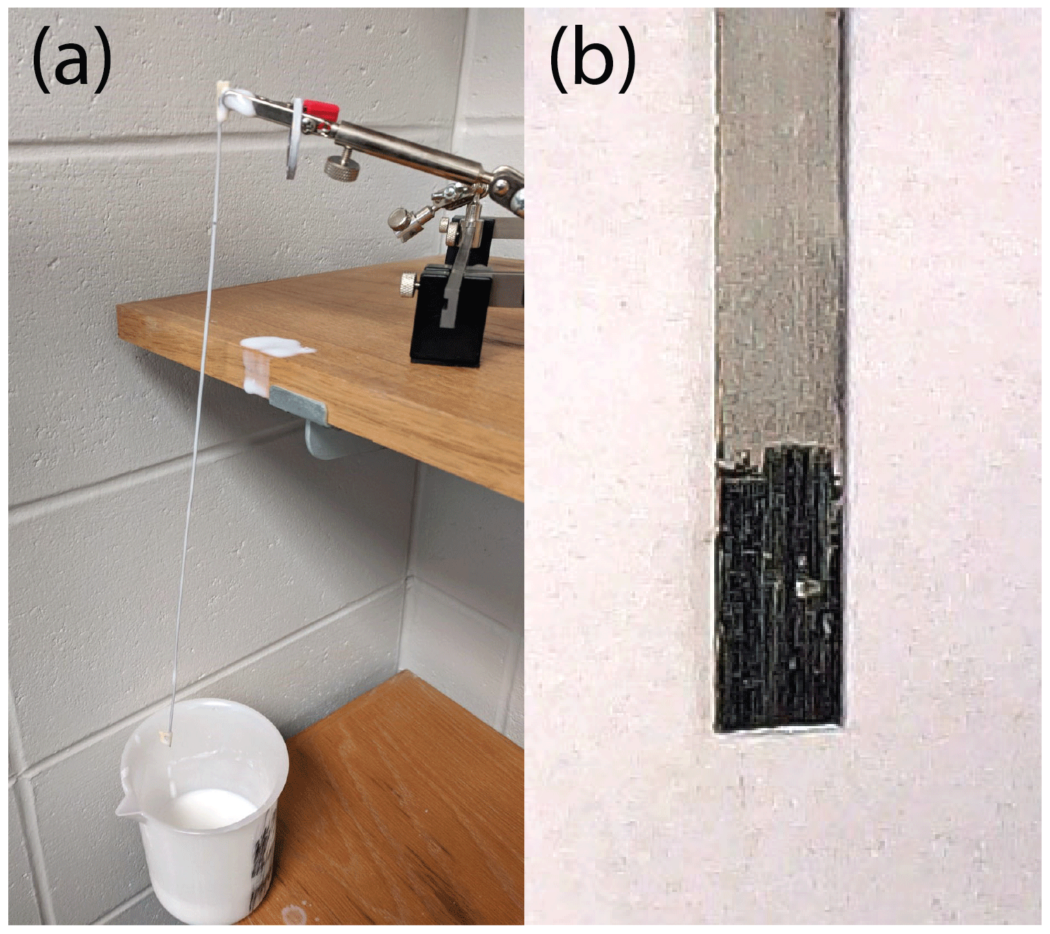
Figure 8(a) An oxide layer is formed by dip coating with milk of magnesia, which forms magnesium oxide during heat treatment. (b) Close-up of a strip of cold-rolled permalloy strip showing milk of magnesia coating and a cleared region for welding.
2.3 Manufacturing a ring-core assembly
The ferromagnetic element of the ring core was made up of insulated permalloy strip spirally wound onto the Inconel bobbin. Depending on the foil available, some sensors used one continuous strip, while others used several strips welded together to be long enough for six turns on the Inconel bobbin (Fig. 9a). The end of the permalloy strip was spot-welded to the bottom of the channel cut into the outer circumference of the bobbin. The strip was cut to length such that the start and end of the strip were aligned. The ends of the permalloy strip created an unwanted magnetic asymmetry in the ring core that manifested in the output of the sensor. Aligning the start and end of the strip localized this asymmetry, allowing the sensor output to be tuned for maximum symmetry by rotating the ring core within the sense winding. In the case of double-wound sensors, this procedure could be carried out for the first (inner) sense winding prior to affixing the second (outer) sense winding. The spiral winding was terminated by scraping away a small amount of the oxide layer (Fig. 9b) and spot-welding the end of the strip down to the layer immediately underneath (Fig. 9c). A similar method of assembling rings is described in Musmann (2010). In this case, the foil was wound by hand using a simple jig and the tension was not finely controlled. The 50 cm long permalloy strip used in a six-layer core had a resistance of about 1.8 Ω. After spot-welding such a strip on a bobbin, the resistance between the outer spot-weld and the bobbin was lower than 0.5 Ω, indicating that there were more than two spot-welds within the core. The consequences of these additional welds are unclear and alternative methods of affixing the foil are being investigated.

Figure 9(a) Permalloy strips joined by spot-welding. (b) Permalloy strip wound onto bobbin ready for final weld (note patch of removed magnesia coating). (c) Permalloy strip spot-welded to itself to finish the spiral wind.
2.4 Heat treatment of the ring-core assembly
The assembled fluxgate ring cores were heat-treated to produce high-permeability, low-coercivity, and repeatable re-magnetization properties in the ferromagnetic material that the authors hypothesize produced a relatively stress-free crystalline structure and therefore low magnetic noise. This approach was guided by the theory of the origin of fluxgate magnetic noise developed in Narod (2014). The heat treatment was intended to develop the largest possible grains in the given thickness of the permalloy foil without developing undesirable fabric in which the easy axes directions are misaligned with respect to the desired magnetizing direction (e.g., Major and Martin, 1970; Odani, 1964).
In contrast, Gorobei and Gorobei (1981) showed experimentally that a low-temperature (800 ∘C) annealing of nickel–molybdenum alloys yields a lower noise level than the high-temperature (1000, 1150 ∘C) annealing recommended in Gordon et al. (1968). Further study is needed to understand what material process causes what noise result. The discrepancy between Couderchon et al. (1989) and Müller et al. (1998) is striking. An 800 ∘C treatment that is purely secondary recrystallization may well be optimal for smaller grain materials, but this would need to be investigated.
Figure 10a shows a generic temperature profile for a ring core showing a rapid heating from ambient temperature (A–B), a high-temperature dwell (B–C), a controlled ramp-down (C–D), and a slow ramp through the disordering range and down to ambient temperature (D–E). The furnace had a maximum thermal slew rate due to its heating power, thermal mass, and potential for thermal-shock failure of the work tube that prevented it from rapidly heating from ambient to the dwell temperature. To circumvent this, the furnace was programmed to execute a slower temperature increase, and once the furnace had reached the desired peak dwell temperature, the ring cores were rapidly inserted into the hot zone using a mobile loading plate as illustrated in Fig. 12. Rapid heating had the effect of maximizing grain growth due to primary recrystallization. A factor as much as 10 times larger in average grain size volume is achievable by rapid compared to slow heating.
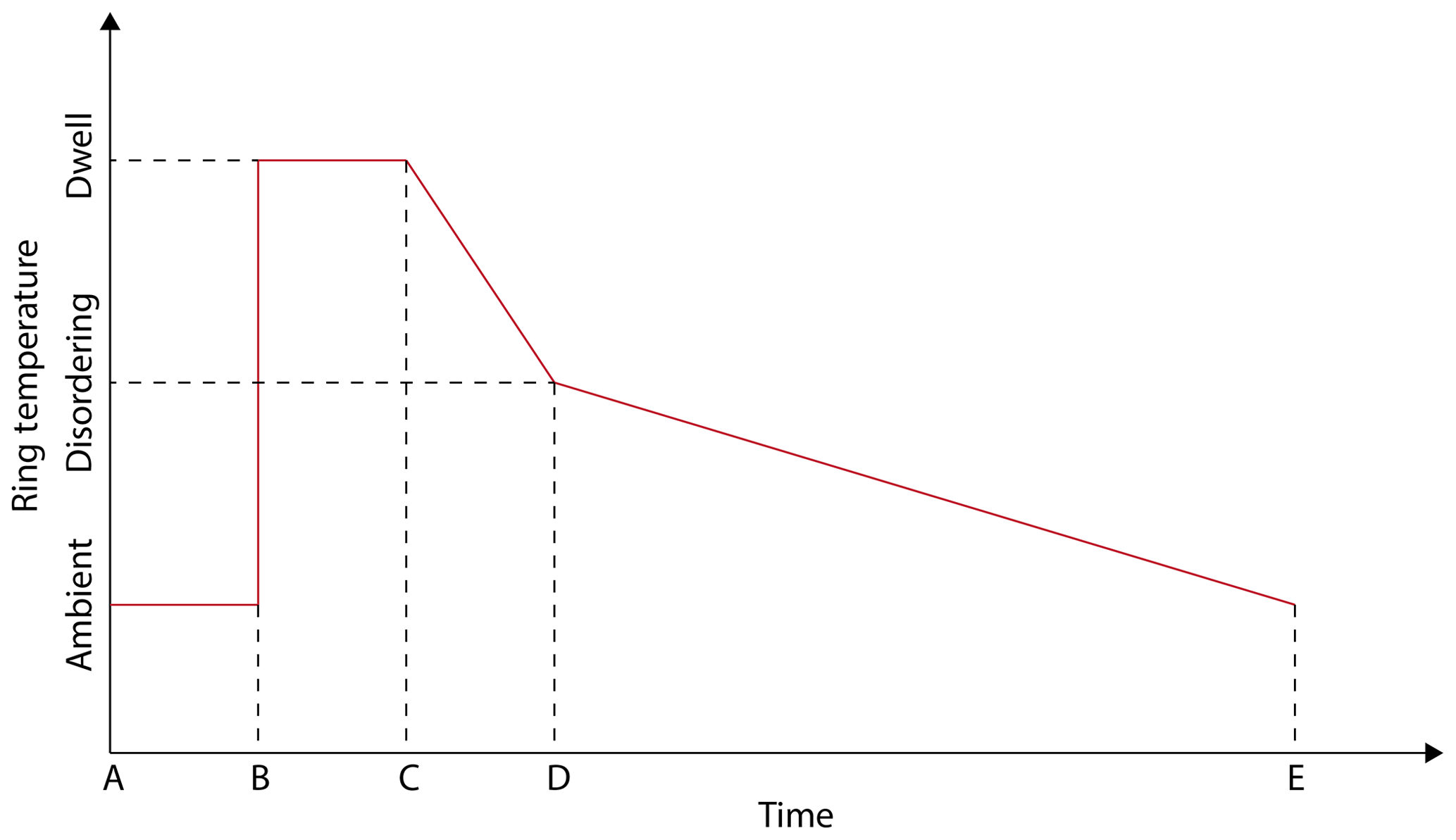
Figure 10Example heat profile for a ring core showing a rapid heating from ambient temperature (A–B), a high-temperature dwell (B–C), a controlled ramp-down (C–D), and a slow ramp through the disordering range and down to ambient temperature (D–E).
At the dwell temperature, the mechanical stress embedded in cold-rolled permalloy strips is believed to enhance primary recrystallization of the heat-treated material. The ring cores were heat-treated in a protective (oxygen-free) atmosphere produced by a gas mixture of 5 % hydrogen and 95 % argon continuously injected at 100 mL min−1. The hydrogen was intended to prevent the formation of oxides and to react with and remove light element impurities in the permalloy strips. The hydrogen was diluted in argon to mitigate the risk of explosion.
The heat profile shown in Fig. 10 was drawn loosely from that given by Gordon et al. (1968). The dwell temperature and duration were determined empirically based on test ring cores constructed from 100 µm 6-81 permalloy strip, processed at dwell temperatures in the range of 1100 to 1200 ∘C, and subsequent measurements of their magnetic noise. The ideal dwell temperature and duration would enable complete primary recrystallization but minimize secondary recrystallization whereby a small number of grains grow at the expense of many other primary recrystallized grains. This grain growth depends on the thickness of the permalloy strip and hence would not be expected to be the same for the 100 µm strip used and the historical 3–12 µm strips. The optimum temperature was not well constrained; performance over a wide range of dwell temperatures has not yet been assessed in detail and is the subject of ongoing work. The C–D cooling rate is thought to be noncritical and was completed as a furnace cool (i.e., the fastest rate that could be safely executed by the furnace). In this case, −35 ∘C per hour was used to reduce the risk of cracking to the ceramic work tube. Gordon et al. (1968) defined the critical ordering range for 6-81 permalloy to be from 600 to 400 ∘C. The D–E cooling rate was −22.5 ∘C per hour compared to −35 ∘C per hour in Gordon et al. (1968). The impact of this slower cooling rate on the magnetic noise of the ring cores has not yet been explored.
2.5 Heat-treatment process furnace setup
Ring-core heat treatment was undertaken using a modified Carbolite Gero STF160 tube furnace configured for operation with a hydrogen atmosphere. The furnace was adapted, as shown schematically in Fig. 10a, by the addition of a loading chamber where ring cores could be staged at room temperature while the furnace heated and then rapidly inserted into the hot zone without violating the controlled atmosphere. A complete heat-treatment system setup consisted of a furnace, gas cabinet, ring-core loading chamber, transport system, and data acquisition system. Figure 11 shows a diagram and a photograph of the heat-treatment system used at the University of Alberta.

Figure 11Diagram (a) and photograph (b) of the heat-treatment system, showing the loading chamber and wire pulley used for hot insertion.
The furnace hot zone comprised a work tube of high-purity (99.8 %) alumina that is impermeable and inert to hydrogen. The adaptation for rapid ring-core insertion is shown schematically in Fig. 12. A high-purity alumina Dee tube (Coorstek, AD-998) was inserted into the alumina work tube to create a flat surface on which parts could move. The heat plug at the end of the work tube adjacent to the loading chamber was modified to create an opening aligned with the surface of the Dee tube through which the ring cores could be inserted. In the loading chamber, aluminum tubes coplanar with the surface of the Dee tube created the staging area for the ring cores.
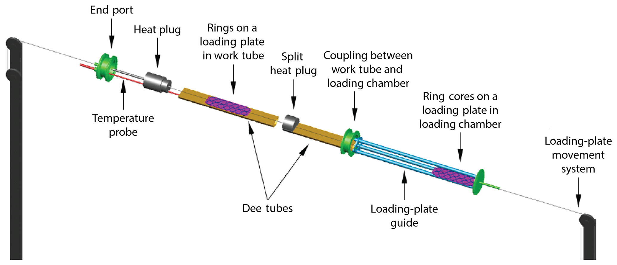
Figure 12Exploded view of the internal components of the furnace and the loading chamber. Ring cores were staged in the loading chamber for rapid insertion after the furnace reached the nominal dwell temperature.
The ring cores were placed on a molybdenum loading plate (Fig. 13) that could be pulled into the hot zone using tungsten wire threaded through the length of the work tube. Alumina powder was used to prevent the ring cores from welding to the loading plate during the heat treatment.
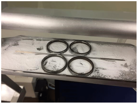
Figure 13Ring cores on a molybdenum loading plate in a loading chamber. Alumina powder prevented the ring cores from welding to the plate.
The heat treatment had significant effects on the crystalline structure of permalloy strips as shown in Fig. 14. The width (horizontal dimension) of the permalloy strip in each photograph is about 1.57 mm. The correlation between grain size and the magnetic noise of permalloy ring cores in fluxgate sensors continues to be investigated. Larger grains are believed to produce less magnetic noise but only if they grow through primary recrystallization (Herzer, 1997). Further research on this topic is needed.
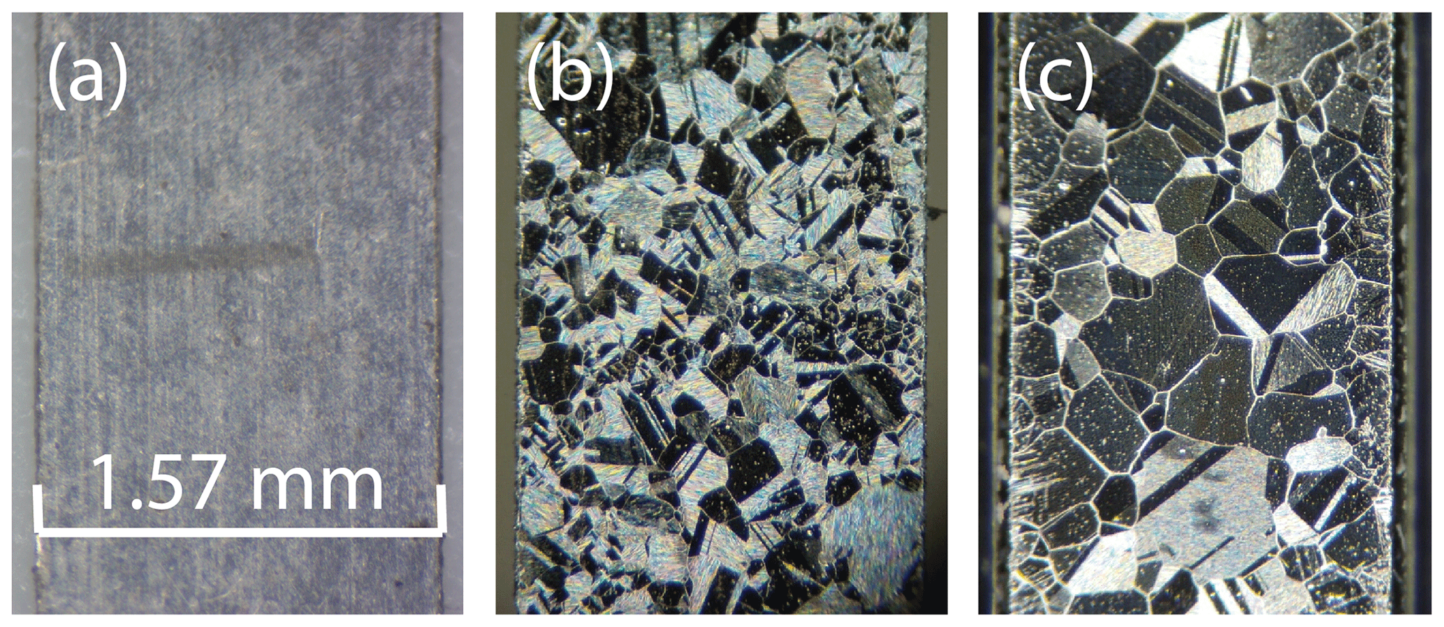
Figure 14Optical image of permalloy grains (a) before heat treatment and after heat treatment at (b) 1150 ∘C and (c) 1200 ∘C.
The effect of the heat treatment on the magnetic properties of the permalloy was tested by examining the B–H curves of heat-treated test strips. The strips were cyclically re-magnetized by supplying a 1 kHz sinusoidal voltage to a drive winding. Each magnetization cycle was captured in 250 k readings of magnetizing current and coil-induced voltage. B values were derived from dB∕dt values through numerical integration and are shown in arbitrary units (AUs). Figure 15 shows the effect of a heat treatment on B–H curves of a single, straight permalloy strip ( mm) excited at 1 kHz and averaged over 400 magnetization cycles.
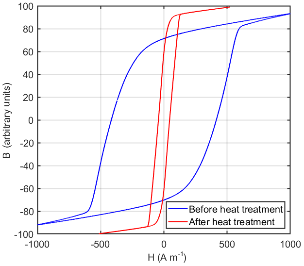
The heat treatment reduced the coercivity of the permalloy strip by a factor of about 6. It seems likely that heat treatments can be further optimized in terms of dwell temperature, dwell time, and cooling rates; this is still being investigated. The ideal and optimized thermal profile for heat treatment is also likely to depend on the permalloy thickness.
The new ring cores were integrated into a fully working fluxgate magnetometer to assess their noise performance. Each ring core was given a toroidal drive winding of ∼232 turns of 32 AWG enameled wire to drive the ferromagnetic element of the ring cores into periodic magnetic saturation. The wound ring cores were each mounted on a small printed circuit board for efficient and repeatable testing. Each ring core was rotated within a 360-turn sense winding to minimize the coupling of the drive signal into the sensor output. Figure 16 shows the custom fixture used for testing the ring cores.
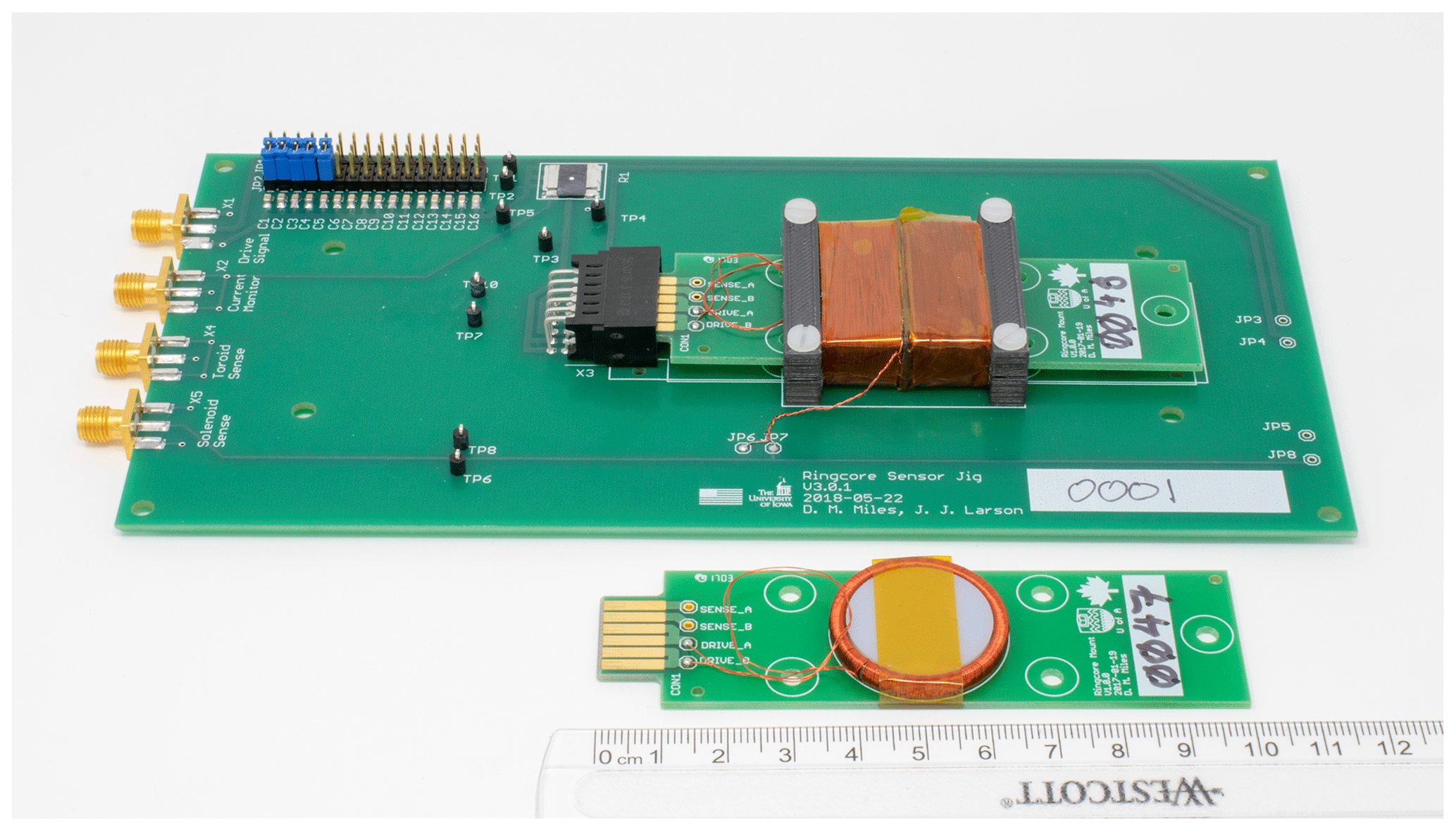
Figure 16Test jig used to rapidly characterize multiple ring cores. Each ring core has a toroidal drive winding applied and is mounted on a small printed circuit board. The mounted ring core inserts through a modified sense winding and the entire assembly is placed in a solenoid–magnetic shield for testing.
The fluxgate ring cores were characterized by driving and interrogating them with a fluxgate magnetometer electronics package based on a heritage design (Miles et al., 2013, 2016; Narod and Bennest, 1990; Wallis et al., 2015) utilizing a second-harmonic-tuned drive with direct digitization (Fig. 17a), which had been generalized to drive and interrogate a wide range of ring cores.
Figure 17b shows a single-axis laboratory fluxgate electronics design built for this project. The magnetometer operated on external benchtop voltage supplies, allowing the ring-core drive signal to be rapidly optimized for different ring-core designs. The sequence of large power inductors, visible on the right half of the circuit board, combined with a similar capacitor bank on the sensor fixture and custom firmware, allowed the drive circuit to be rapidly tuned to achieve the rapid and deep magnetic saturation required for low-noise operation.
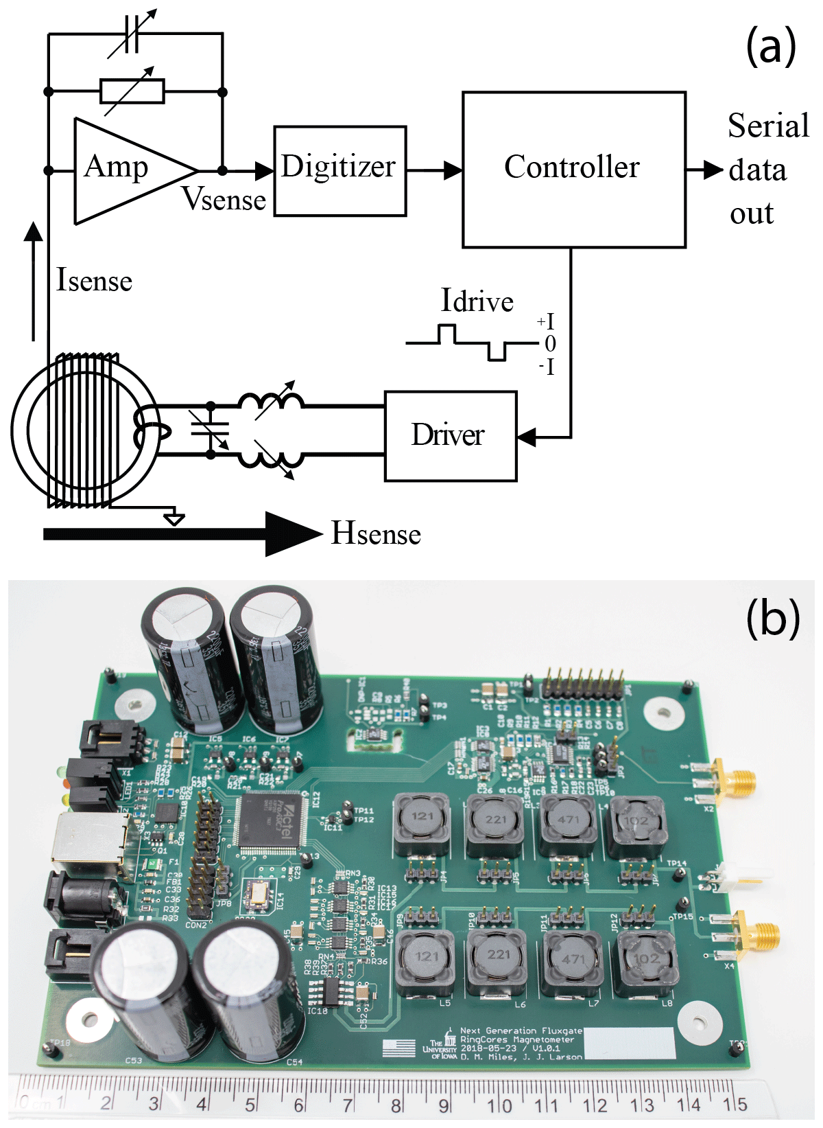
Figure 17Simplified functional diagram (a) and photograph (b) of one fluxgate magnetometer channel with a configurable drive and preamplifier.
The ring cores were driven at 5 kHz and tuned to create large-amplitude and short-duration current spikes (Fig. 18a). The sense winding was used in a short-circuit current-output configuration, creating waveforms at the output of the preamplifier as shown in Fig. 18b. The ambient magnetic field created second harmonic modulation that was sampled using synchronous digitization indicated by the vertical dashed red lines in the figure.
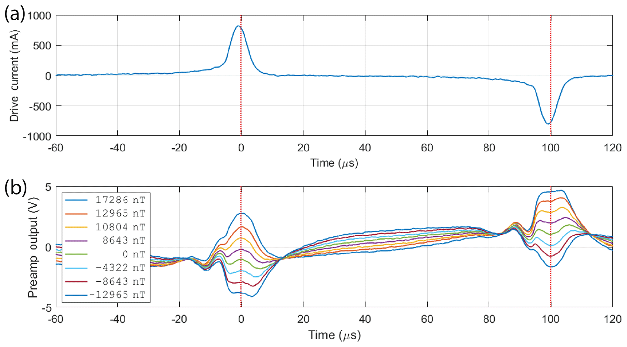
Figure 18(a) The current wave from the tuned drive circuit ensures that the ring cores are in deep magnetic saturation. (b) Time series of the sense-coil output after the preamplifier, showing the response to different magnetic field intensities.
The ring cores were characterized for noise performance, aging effects, and for basic thermal and vibration flight qualification. The noise floor of each ring core was calculated by calibrating the coupled ring–sensor–electronics against a known magnetic field using a solenoid inside a magnetic shield. The solenoid was then switched off and 20 min of 100 sps magnetically quiet data were recorded and processed to produce power spectral density (PSD) using a unit-correct quantitative implementation of Welch's method (Heinzel et al., 2002; Welch, 1967) with a 2048-point fast Fourier transform (FFT), a 1536-point overlap, and a Hann window function, giving a power spectral density estimation down to ∼0.1 Hz. The figure of merit for each ring core was taken to be the value at 1 Hz of a line fit to the low-frequency (1∕f) region of the quiet data PSD, giving a quantitative estimate of the magnetic noise at 1 Hz.
A total of 22 ring cores were manufactured using the process described herein and heat-treated in three batches of 2, 10, and 10. The average power spectral noise density was very similar in ring cores from all three batches, with variability decreasing slightly in the final batch, likely because of improved consistency in spot-welding the permalloy strips. Figure 19 shows a histogram for the noise level of these ring cores compared to those for historical 3 and 12 µm Infinetics ring cores. The noise measurements were performed in a three-layer mumetal magnetic shield with a residual field strength of ∼50 nT.
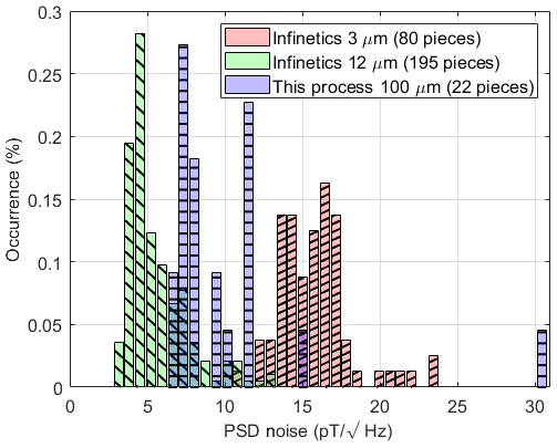
Figure 19Histogram of ring-core noise (pT Hz) at 1 Hz. The current process yields 6–11 pT Hz at 1 Hz noise performance compared to ∼4 for the Infinetics 12 µm ring cores and ∼16 for the 3 µm Infinetics ring cores.
The number of ring cores produced by the current process was lower (22 pieces) than for the Infinetics 3 µm (80 pieces) and 12 µm (195 pieces) processes available for comparison. The current process primarily yielded ring cores with a noise of 6–11 pT Hz at 1 Hz. The most recent batch of 10 ring cores had a median magnetic noise of 7.5 pT Hz at 1 Hz with a standard deviation of 2.5 pT Hz. A subset of six ring cores underwent a nominal spaceflight survival qualification testing, which consisted of exposure to vacuum, vibration testing, and eight thermal cycles from −60 to +75 ∘C. The performance of the six ring cores was tested before and after this testing and was not negatively impacted.
Our work towards developing a well-defined and reliable method for manufacturing low-noise fluxgate sensors for space physics and geophysics uses has generally followed on the efforts undertaken by the Naval Ordinance Laboratory in the 1960s (Gordon et al., 1968), the commonalities being the use of 6-81 Mo permalloy as the principal material, as well as its processing by cold deformation and specific heat treatment for the development of large grain structure. However, several other methodologies making use of different materials have also been used for the manufacturing of low-noise fluxgate sensors, with significant success.
Beginning in 1984 with the experimental works of Shirae (1984) and Narod et al. (1985), amorphous, high-cobalt alloys and processes were developed to create fluxgate sensors for both ground- and space-based uses. For example, in the 1990s, Otto Neilson and others at the Danish Technical University (Nielsen et al., 1995) used an amorphous alloy to create the compact spherical coil (CSC) ring-core fluxgate magnetometer aboard the Orsted satellite. Also beginning in the 1990s, Luis Benyoseph of the National Observatory of Brazil has undertaken a long-term experimental effort to improve amorphous alloys for fluxgate sensors (Benyosef, 1996; Benyosef et al., 1995, 2008). More recently, Lajos Varga at the Hungarian Academy of Sciences developed amorphous materials for magnetometry (Lajos K. Varga, personal communication, 2013).
Rapidly quenched amorphous alloys are limited by both their minimum and maximum thicknesses compared with crystalline permalloys. Also, the rapid cooling creates an anisotropy in the cooling direction across the thickness. Both properties may limit their possible performance in magnetometers. Their low Curie temperatures, 200 ∘C or lower, may impact their thermal stability (Acuña, 2002).
In the 1990s investigators in Braunschweig, Berlin, and Dresden developed a low-noise permalloy, again having 6.0 % molybdenum and about 81 % nickel (Müller et al., 1998). The processing of this material was significantly different from our present material. From conversations with Karl-Heinz Fornacon (Karl-Heinz Fornacon, personal communication, 2017) we understand that their heat treatments were performed in a furnace that did not permit the rapid insertion of specimens into the hot zone and that specimens were required to warm up slowly as the furnace was heated. Such a heating curve would eliminate all possibility of grain growth by primary recrystallization occurring, leaving all grain growth to occur via secondary recrystallization (Pfeifer and Radeloff, 1980). It has been believed for a long time that secondary recrystallization is undesirable for the development of magnetic properties (Odani, 1964). Their overall result was that their best material for fluxgate sensors had the smallest grain size of about 10 µm.
Significant work with various permalloys has been published in the Russian language literature (e.g., Afanas'ev, 1986; Afanas'ev et al., 1977; Afanassiev et al., 1980; Musmann, 2010). However, limited details of the heat treatments and grain sizes from the work completed around the 1970s are available in the English language literature.
If one takes as common knowledge that low coercivity and high initial permeability are desirable traits for sensor materials, then there should be merit is seeking materials of very small grain. Herzer (1990, 1992) found that such desirable properties occur at both ends of the grain size spectrum, that is, for grain sizes much smaller than 1 µm or larger than 20 µm. The small grain end of the spectrum gets into the so-called nanocrystalline materials, while the large grain end is the parameter space we have chosen to examine.
The process described herein has been developed so that eventually all the essential steps (melting, rolling, cutting, assembling, heat-treating, calibrating, and testing) should be achievable in-house and in small quantities. This capability is intended to enable future studies to probe the many different design choices that may affect fluxgate performance (metallurgical composition, alloying process, homogenization, reduction method, work hardening, machining and heat affect, geometry, heat-treatment profile, etc.). The authors would like to encourage other researchers to publish as many of these details as is practical to facilitate the meaningful comparison of results between different cores manufactured by different groups using different processes to eventually expose all the critical parameters that enable low-noise, highly stable materials for fluxgate sensors.
Despite their ubiquitous use, the parameters that control the intrinsic magnetic noise of the ferromagnetic element remain poorly understood, and no published process can reproduce the performance of the widely used low-noise Infinetics S1000 ring core. We described a manufacturing approach that can reliably produce an S1000-compatible fluxgate ring core with a noise of 6–11 pT Hz at 1 Hz. The ring core comprised a custom 6-81 permalloy, cold-rolled to 100 µm, coated with an insulator, spirally wound onto a circular bobbin, and heat-treated in a reducing atmosphere. The manufacturing process described here is unlikely to be either a local or global optimum in the ring-core parameter space. However, it does reproduce performance comparable to the legacy S1000 ring core that underpins many modern instruments. As a result, our team has established a process that can provide an ongoing supply of scientifically useful low-noise ring cores, which will ensure an ongoing supply of high-quality science-grade fluxgate magnetometer instruments.
Ongoing research into optimizing this process and new low-noise materials and sensors is being conducted with the goal of ∼1 pT Hz at 1 Hz noise levels. Research is in progress to explore parameters such as alternative ring-core geometries (including racetracks and parallel rods), the constituents and makeup of the permalloy, the use of geometries such as wire rather than strips, the permalloy thickness, the necessity of work hardening the ferromagnetic material before heat-treating, the impact of 100 % versus 5 % hydrogen in the heat-treatment atmosphere, the rate of heating to the dwell temperature, the temperature and duration of the dwell, the rate of cooling from dwell to the disordering temperature, and the rate of cooling from the disordering temperature to room temperature. The high-noise outliers reported here suggest that there are some as yet poorly controlled manufacturing variables with a significant negative impact on the ring-core noise. An obvious potential way to improve the repeatability of the manufacturing process would be an improved way to affix the permalloy strip onto the bobbin. Experiments to evaluate other ring-core construction techniques, such as solid permalloy washers rather than spiral-wound tape, are in progress. The presented work has focused on manufacturing ring cores that meet the commonly accepted noise level of <10 pT Hz at 1 Hz. Future work will need to the include investigation of other performance metrics including changes in the offset stability, gain, and noise of the ring core with temperature.
The data and source code used in the creation of this paper can be accessed by contacting the authors.
DMM wrote the paper with contributions from all authors. The ring cores presented here were developed at the University of Alberta under a contract led by IRM from the Canadian Space Agency. DMM developed and built the experimental apparatus to characterize the new ring cores. BBN primarily completed the literature review on the ring-core physics and developed the heat treatment presented here. JRB provided guidance on the ring-core manufacturing process. MC and DB designed, constructed, and operated the heat-treatment system. AK primarily characterized ring cores. MRL completed preliminary tests of the ring-core manufacturing process. DKM primarily provided guidance on testing and characterizing ring-core performance. JL built, assembled, and tested infrastructure at the University of Iowa used to characterize and document ring cores for this paper.
B. Barry Narod operated Narod Geophysics Ltd., which manufactured fluxgate magnetometers until the company ceased production operation in 2008. John R. Bennest operated Bennest Enterprises Ltd., which manufactured a variety of custom scientific instruments and equipment, including fluxgate magnetometers, until the company ceased operations in 2018.
Work on the project was supported by the Canadian Space Agency under contract 9F063-140909/006/MTB_PT6_Ring-cores. David M. Miles was subsequently supported by faculty start-up funding from the University of Iowa. Ian R. Mann is supported by a Discovery Grant from Canadian NSERC. The authors wish to thank Richard Dvorsky, Michael Webb, Christian Hansen, and Spencer Kuhl for developing, manufacturing, and documenting the ring cores shown in this paper.
This research has been supported by the Canadian Space Agency (grant no. 9F063-140909/006/MTB_PT6_Ring-cores), the University of Iowa (faculty start-up grant), and the Natural Sciences and Engineering Research Council of Canada (Discovery Grant).
This paper was edited by Valery Korepanov and reviewed by two anonymous referees.
Acuña, M. H.: Space-based magnetometers, Rev. Sci. Instrum., 73, 3717–3736, 2002.
Acuña, M. H., Scearce, C. S., Seek, J., and Scheifele, J.: The MAGSAT vector magnetometer: A precision fluxgate magnetometer for the measurement of the geomagnetic field, National Aeronautics and Space Administration, 1978.
Afanas'ev, I. V.: Ferrozondovye pribory, Energoatomizdat, Leningradskoe otd-nie, Leningrad, 1986.
Afanas'ev, Y. V., Gorobei, V. N., Mart'yanova, K. D., Pluchek, B. Y., Sosnin, V. V., and Shcherbakova, T. I.: Low-noise iron-nickel alloys for cores of ferromagnetic probes and magnetic modulators, Meas. Tech., 20, 1491–1494, https://doi.org/10.1007/BF00824277, 1977.
Afanassiev, Y. V., Gorobei, V. N., Porfirov, V. P., Pluchek, B. Y., Scherbakova, T. I., and Agornik, V. Y.: USSR Copyright (Inventors) Certificate 771580, available at: http://patents.su/3-771580-ustrojjstvo-dlya-izmereniya-parametrov-magnitnogo-polya.html (last access: 3 September 2019), 1980.
Auster, H. U., Glassmeier, K. H., Magnes, W., Aydogar, O., Baumjohann, W., Constantinescu, D., Fischer, D., Fornacon, K. H., Georgescu, E., Harvey, P., Hillenmaier, O., Kroth, R., Ludlam, M., Narita, Y., Nakamura, R., Okrafka, K., Plaschke, F., Richter, I., Schwarzl, H., Stoll, B., Valavanoglou, A., and Wiedemann, M.: The THEMIS Fluxgate Magnetometer, Space Sci. Rev., 141, 235–264, https://doi.org/10.1007/s11214-008-9365-9, 2008.
Benyosef, L. C. C.: Effect of Stresses on the Magnetic Properties of Amorphous Ribbons for Fluxgate magnetometers, Transl.-VE RIECANSKY, 1996.
Benyosef, L. C. C., Teodósio, J. R., Taranichev, V. E., and Jalnin, B. V.: Improvements on CoFeSiB amorphous ribbon for fluxgate sensor cores, Scripta Metall. Mater., 33, 1451–1454, 1995.
Benyosef, L. C. C., Stael, G. C., and Bochner, M.: Optimization of the magnetic properties of materials for fluxgate sensors, Mater. Res., 11, 145–149, https://doi.org/10.1590/S1516-14392008000200006, 2008.
Carr, C., Brown, P., Zhang, T. L., Gloag, J., Horbury, T., Lucek, E., Magnes, W., O'Brien, H., Oddy, T., Auster, U., Austin, P., Aydogar, O., Balogh, A., Baumjohann, W., Beek, T., Eichelberger, H., Fornacon, K.-H., Georgescu, E., Glassmeier, K.-H., Ludlam, M., Nakamura, R., and Richter, I.: The Double Star magnetic field investigation: Instrument design, performance and highlights of the first year's observations, Ann. Geophys., 23, 2713–2732, available at: https://hal.archives-ouvertes.fr/hal-00317923/ (last access: 20 September 2016), 2005.
Carr, C. M., Horbury, T. S., Balogh, A., Bale, S. D., Baumjohann, W., Bavassano, B., Breen, A., Burgess, D., Cargill, P. J., Crooker, N., Erdõs, G., Fletcher, L., Forsyth, R. J., Giacalone, J., Glassmeier, K.-H., Hoeksema, J. T., Goldstein, M. L., Lockwood, M., Magnes, W., Maksimovic, M., March, E., Matthaeus, W. H., Murphy, N., Nakariakov, V. M., Pacheco, J. R., Pincon, J.-L., Riley, P., Russell, C. T., Schwartz, S. J., Szabo, A., Thompson, M., Vainio, R., Velli, M., Vennerstrom, S., Walsh, R., Wimmer-Schweingruber, R., and Zank, G.: A Magnetometer for the Solar Orbiter Mission, ESA Publ. Div., Athens, Greece, available at: https://www.researchgate.net/publication/41625175_A_Magnetometer_For_The_Solar_Orbiter_Mission (last access: 3 September 2019), 2007.
Couderchon, G., Porteseil, J. L., Bertotti, G., Fiorillo, F., and Soardo, G. P.: Magnetization process in NiFe alloys with vanishing anisotropies, IEEE T. Magn., 25, 3973–3975, 1989.
Danskin, D. W., St-Louis, B., Yuan, X., McKee, L., Lamothe, M., Calp, D., Parmalee, J., Shaughnessy, R., Trichtchenko, L., and Lam, H.: The CANMOS Magnetometer System and its Space Weather Applications, in: AGU Spring Meeting Abstracts, 2009.
English, A. T. and Chin, G. Y.: Metallurgy and magnetic properties control in permalloy, J. Appl. Phys., 38, 1183–1187, 1967.
Fornacon, K.-H., Auster, H. U., Georgescu, E., Baumjohann, W., Glassmeier, K.-H., Haerendel, G., Rustenbach, J., and Dunlop, M.: The magnetic field experiment onboard Equator-S and its scientific possibilities, Ann. Geophys., 17, 1521–1527, https://doi.org/10.1007/s00585-999-1521-3, 1999.
Geyger, A. W.: The ring-core magnetometer – A new type of second-harmonic flux-gate magnetometer, T. Am. Inst. Electr. Eng. Part Commun. Electron., 81, 65–73, https://doi.org/10.1109/TCE.1962.6373206, 1962.
Geyger, W. A.: New Type of Flux-Gate Magnetometer, J. Appl. Phys., 33, 1280–1281, 1962.
Gordon, D., Lundsten, R., Chiarodo, R. and Helms, H.: A fluxgate sensor of high stability for low field magnetometry, IEEE T. Magn., 4, 397–401, 1968.
Gorobei, V. N. and Gorobei, N. N.: Thermal-activation approach to the study of noise in cores of ferromagnetic probes, Meas. Tech., 24, 1085–1088, https://doi.org/10.1007/BF00828723, 1981.
Heinzel, G., Rüdiger, A., and Schilling, R.: Spectrum and spectral density estimation by the Discrete Fourier transform (DFT), including a comprehensive list of window functions and some new at-top windows, Max-Planck-Institut fur Gravitationsphysik, Teilinstitut Hannover, available at: http://pubman.mpdl.mpg.de/pubman/faces/viewItemOverviewPage.jsp?itemId=escidoc:152164 (last access: 16 September 2016), 2002.
Herzer, G.: Grain size dependence of coercivity and permeability in nanocrystalline ferromagnets, IEEE T. Magn., 26, 1397–1402, 1990.
Herzer, G.: Nanocrystalline soft magnetic materials, J. Magn. Magn. Mater., 112, 258–262, 1992.
Herzer, G.: Amorphous and Nanocrystalline Soft Magnets, in: Magnetic Hysteresis in Novel Magnetic Materials, edited by: Hadjipanayis, G. C., Springer Netherlands, Dordrecht, 711–730, 1997.
Kellock, S., Austin, P., Balogh, A., Gerlach, B., Marquedant, R., Musmann, G., Smith, E., Southwood, D., and Szalai, S.: Cassini dual technique magnetometer instrument (MAG), in: Cassini/Huygens: A Mission to the Saturnian Systems, International Society for Optics and Photonics, 2803, 141–152, 1996.
Major, R. and Martin, M.: The effect of grain orientation on the initial permeability of mumetal strip, IEEE T. Magn., 6, 101–105, 1970.
Mann, I. R., Milling, D. K., Rae, I. J., Ozeke, L. G., Kale, A., Kale, Z. C., Murphy, K. R., Parent, A., Usanova, M., Pahud, D. M., Lee, E.-A., Amalraj, V., Wallis, D. D., Angelopoulos, V., Glassmeier, K.-H., Russell, C. T., Auster, H.-U., and Singer, H. J.: The Upgraded CARISMA Magnetometer Array in the THEMIS Era, Space Sci. Rev., 141, 413–451, https://doi.org/10.1007/s11214-008-9457-6, 2008.
Miles, D. M., Bennest, J. R., Mann, I. R., and Millling, D. K.: A radiation hardened digital fluxgate magnetometer for space applications, Geosci. Instrum. Method. Data Syst., 2, 213–224, https://doi.org/10.5194/gi-2-213-2013, 2013.
Miles, D. M., Mann, I. R., Ciurzynsky, M., Barona, D., Narod, B. B., Bennest, J. R., Pakhotin, I. P., Kale, A., Bruner, B., Nokes, C. D. A., Cupido, C., Haluza-DeLay, T., Elliott, D. G., and Milling, D. K.: A miniature, low-power scientific fluxgate magnetometer: A stepping-stone to cube-satellite constellation missions, J. Geophys. Res.-Space, 121, 11839–11860, https://doi.org/10.1002/2016JA023147, 2016.
Miles, D. M., Mann, I. R., Kale, A., Milling, D. K., Narod, B. B., Bennest, J. R., Barona, D., and Unsworth, M. J.: The effect of winding and core support material on the thermal gain dependence of a fluxgate magnetometer sensor, Geosci. Instrum. Method. Data Syst., 6, 377–396, https://doi.org/10.5194/gi-6-377-2017, 2017.
Müller, M., Lederer, T., Fornacon, K. H., and Schäfer, R.: Grain structure, coercivity and high-frequency noise in soft magnetic Fe81Ni6Mo alloys, J. Magn. Magn. Mater., 177, 231–232, 1998.
Musmann, G.: Fluxgate magnetometers for space research, BoD – Books on Demand, 2010.
Narod, B. B.: The origin of noise and magnetic hysteresis in crystalline permalloy ring-core fluxgate sensors, Geosci. Instrum. Method. Data Syst., 3, 201–210, https://doi.org/10.5194/gi-3-201-2014, 2014.
Narod, B. B. and Bennest, J. R.: Ring-core fluxgate magnetometers for use as observatory variometers, Phys. Earth Planet. In., 59, 23–28, 1990.
Narod, B. B., Bennest, J. R., Strom-Olsen, J. O., Nezil, F., and Dunlap, R. A.: An evaluation of the noise performance of Fe, Co, Si, and B amorphous alloys in ring-core fluxgate magnetometers, Can. J. Phys., 63, 1468–1472, 1985.
Nielsen, O. V., Petersen, J. R., Primdahl, F., Brauer, P., Hernando, B., Fernandez, A., Merayo, J. M. G., and Ripka, P.: Development, construction and analysis of the “OErsted” fluxgate magnetometer, Meas. Sci. Technol., 6, 1099, https://doi.org/10.1088/0957-0233/6/8/004, 1995.
Odani, Y.: Magnetic Properties of Cube-Textured 6-81.3 Mo – Permalloy, J. Appl. Phys., 35, 865–866, 1964.
Pfeifer, F.: Zum Verständnis der magnetischen Eigenschaften technischer Permalloylegierungen, Z. Metallkd., 57, 295–300, 1966.
Pfeifer, F. and Boll, R.: New soft magnetic alloys for applications in modern electrotechnics and electronics, IEEE T. Magn., 5, 365–370, 1969.
Pfeifer, F. and Kunz, W.: Bedeutung von kornstruktur und fremdkörpereinschlüssen für die magnetisierungseigenschaften hochpermeabler Ni-Fe-legierungen, J. Magn. Magn. Mater., 4, 214–219, 1977.
Pfeifer, F. and Radeloff, C.: Soft magnetic Ni-Fe and Co-Fe alloys-some physical and metallurgical aspects, J. Magn. Magn. Mater., 19, 190–207, 1980.
Primdahl, F.: The fluxgate magnetometer F Primdahl, J. Phys., 12, 241–253, https://doi.org/10.1088/0022-3735/12/4/001, 1979.
Scanlon, W. W.: Solid state research of the Applied Physics Department for the year 1965, Naval ordnance lab white oak MD, 1966.
Scarzello, J. F., Holmes, J. J., and O'keefe, E. C.: Integrating fluxgate magnetometer, United States patent US 6,278,272, 21 August 2001.
Schultz, A.: EMScope: a continental scale magnetotelluric observatory and data discovery resource, Data Sci. J., 8, IGY6–IGY20, 2009.
Shirae, K.: Noise in amorphous magnetic materials, IEEE T. Magn., 20, 1299–1301, 1984.
Wallis, D. D., Miles, D. M., Narod, B. B., Bennest, J. R., Murphy, K. R., Mann, I. R., and Yau, A. W.: The CASSIOPE/e-POP Magnetic Field Instrument (MGF), Space Sci. Rev., 189, 27–39, https://doi.org/10.1007/s11214-014-0105-z, 2015.
Welch, P. D.: The use of fast Fourier transform for the estimation of power spectra: A method based on time averaging over short, modified periodograms, IEEE T. Audio Electroacoustics, 15, 70–73, 1967.
- Abstract
- Introduction
- Construction and heat treatment of new ring cores
- Effect of heat treatment on permalloy foil strips
- Ring-core characterization
- Performance of the ring cores
- Discussion
- Summary and conclusions
- Future work
- Code and data availability
- Author contributions
- Competing interests
- Acknowledgements
- Financial support
- Review statement
- References