the Creative Commons Attribution 4.0 License.
the Creative Commons Attribution 4.0 License.
 | 13 Sep 2019
Development of a new distributed hybrid seismic and electrical data acquisition station based on system-on-a-programmable-chip technology
Qisheng Zhang
Feng Guo
Zhenzhong Yuan
Shuaiqing Qiao
Qimao Zhang
In the past few decades, with the continuous advancement of technology, seismic and electrical instruments have developed rapidly. However, complex and harsh exploration environments led to higher requirements and severe challenges for traditional geophysical exploration methods and instruments. Therefore, it is extremely urgent to develop new high-precision exploration instruments and data acquisition systems. In this study, a new distributed seismic and electrical hybrid acquisition station is developed using system-on-a-programmable-chip (SoPC) technology. The acquisition station hardware includes an analog board and a main control board. The analog board uses a signal conditioning circuit and a 24-bit analog-to-digital converter (ADS1271) to achieve high-precision data acquisition, while the main control board uses a low-power SoPC to enable high-speed stable data transmission. We designed the data transmission protocol for the acquisition station and developed independently an improved low-voltage differential signaling data transmission technology. What's more, a method to enhance the precision of synchronous acquisition was studied in depth. These key technologies, which were developed for the acquisition station, were integrated into the SoPC of the main control board. Test results indicate that the synchronization precision of the acquisition station is better than 200 ns, and the maximum low-power data transmission speed is 16 Mbps along a 55 m cable. The developed acquisition station has the advantages of low noise, large dynamic range, low power consumption, etc., and it can achieve high-precision hybrid acquisition of seismic and electrical data.


Geophysics is a discipline in which physics principles, methods, and instruments are applied to research and understanding of the Earth structures. It plays an important role in the exploration of energy and mineral resources (Liu, 2017). The advancement of Earth science is inseparable from high-end geoscience instruments (Liu, 2013). As early as the 1970s, the French company Sercel had already introduced the SN338 digital seismograph and its single-station single-channel acquisition station (Huang and Yu, 1994). Presently, the most advanced seismic data acquisition systems in the world, such as Sercel's 508XT system, INOVA's G3i HD system, or FireFly's DR31 system, are working in the field. The 508XT system uses intelligent network technology to achieve autonomous acquisition and local storage, as well as real-time quality control and data transmission to the central recording unit (Van et al., 2001; Mrmureanu et al., 2011). In 2018, Dynamic Technologies (DTCC) group launched the industry's first intelligent seismic sensor, SmartSolo, which integrates high-sensitivity geophones with acquisition circuits, and thus possesses advantages such as its compact size, light weight, and low cost. Bureau of Geophysical Prospecting (BGP) of the China National Petroleum Corporation (CNPC) has developed a new generation of seismic exploration node instruments, eSeis1.0. The Institute of Geology and Geophysics of the Chinese Academy of Sciences has designed, based on a computer network, a digital seismic acquisition system with low power consumption that is capable of data transmission through thousands of channels. Jilin University developed a wired telemetry seismograph, GEIST 438, using an Ethernet relay solution, while the University of Science and Technology of China, Hefei, Anhui, adopted a long-distance Ethernet physical layer technology to achieve a peak transmission rate of 40 Mbps (Qiao et al., 2018; Zhang et al., 2017; Guo et al., 2012; Zhang, 2007; Zhang et al., 2013). In terms of electrical exploration, the theory of electrical detection has developed rapidly and electrical equipment technology and instrumentation have also advanced during the past decades. Representative electrical exploration instruments – such as the GEODE EM3D system from US company Geometrics for the controlled source audio-frequency magnetotellurics (CSAMT) method, the KMS-820 system from US company KMS, the GDP series multifunction electrical instrument from US company Zonge, the eighth generation system V8 from Canadian company Phoenix, the distributed transient electromagnetic system GEOFERRET from Australian company WMC, and the ADU-08E system from German company Metronix – have been widely used. At the same time, relevant technical indicators of the surface electromagnetic prospecting (SEP) system completed by the Institute of Geology and Geophysics in collaboration with the Institute of Electronics of the Chinese Academy of Sciences have reached an international standard (Chen et al., 2018, 2010; Di et al., 2013; Lin et al., 2014; Cheng et al., 2019). Modern seismic and electrical exploration instruments have reached a high level in terms of performance, stability, and industrialization, and they are being developed to achieve intelligence and multi-functionality.
After several decades of resource exploration and exploitation, the energy resources on the surface of the Earth are diminishing, and oil and gas exploration has now encountered a difficult stage in the world. Increasingly complex geological areas and severe exploration environments bring new challenges to traditional geophysical exploration methods and instruments. Seismic and electrical exploration are the two most common geophysical methods currently used for prospecting. Seismic exploration is used to probe great depths and is extremely precise and highly resolved. Hence, it is widely used in the oil and gas industry, groundwater and geothermal resource exploration, and urban underground pipeline detection. However, its use in mining regions with poorly defined strata leads to dramatic lateral signal variations and low signal-to-noise ratios (SNRs). Electrical exploration has been rapidly developed and adopted in mineral resource prospecting, engineering surveys, and environmental surveys. However, these techniques are not sufficient to research the fine ground structures because of limitations in vertical resolution of electrical exploration.
To make better use of various exploration methods, so as to reduce the ambiguity of the solution by the joint inversion of seismic and electrical methods, an integrated seismic and electrical hybrid acquisition technology is proposed. High-resolution hybrid seismic and electrical data acquisition, high-precision synchronization, and high-speed data transmission under low-power conditions are big challenges. Therefore, the development of a new seismic and electrical hybrid acquisition station is of great significance for improving the level of geophysical equipment and promoting the development of combined seismic and electrical exploration technology.
2.1 System-on-a-programmable-chip technology
US company Altera Corporation first introduced system-on-a-programmable-chip (SoPC) technology in 2000. A SoPC is a flexible and highly efficient system-on-a-chip (SoC) solution which integrates functional modules required by the system, such as a processor, I/O interface, hardware accelerator, memory, etc., into a field-programmable gate array (FPGA) device to form a programmable SoC (Astarloa et al., 2005). A SoPC provides developers with a flexible design approach with several advantages, such as low power consumption, easy upgrades and modifications, and both its hardware and software are programmable (Zhang et al., 2012). In this study, SoPC technology is used to design a new hybrid seismic and electrical acquisition station. The advantages of SoPC technology improve the overall performance of the acquisition station.
2.2 Components of the distributed telemetry data acquisition system
The distributed telemetry data acquisition system mainly consists of sensors, acquisition stations, power stations, interconnection stations, a central station, and communication cables. Figure 1 shows a block diagram of the system in which sensors and acquisition stations form the front-end acquisition device, acquisition stations, and power stations are connected by cables, while interconnection stations and the central station, as well as the interconnection stations themselves, are connected by optical fibers. Power stations and interconnection stations power the acquisition stations through power over Ethernet (PoE) and simultaneously carry out acquisition data transfer. The central station monitors the operation of the entire acquisition system and performs data recovery (Wang, 2010).

Figure 1Block diagram of the distributed telemetry data acquisition system. AS, acquisition station; PS, power station; IS, interconnection station; CS, central station.
2.3 Overall framework of the new distributed hybrid seismic and electrical data acquisition station based on SoPC technology
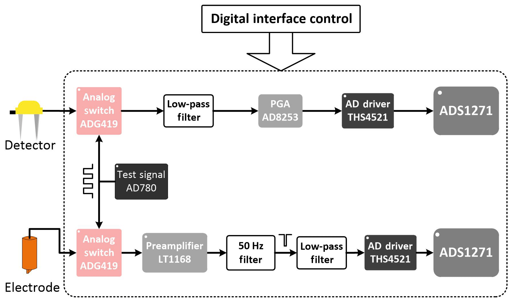
The acquisition station is the key unit for obtaining seismic and electrical data. Figure 2 shows the overall architecture of the acquisition station developed in this study, which adopts ADS1271+SoPC to achieve high-precision analog-to-digital conversion and high-speed real-time data transmission. The clock of the ADS1271 is divided by the high-precision clock source of the SoPC. The SoPC controls the ADS1271 through the serial peripheral interface (SPI) protocol, and uses the synchronization signal of the ADS1271 to realize synchronous data acquisition of each channel. At the same time, we know that the data of the delta-sigma ADC (analog to digital converter) that just started to collect is unrealistic. We performed corresponding operations during data processing to ensure the authenticity and validity of the data. SoPC uses FIFO (“first in, first out”) to buffer data, avoiding the frequent interruption of ADC work. Analog signal output by sensors (detectors or electrodes) is passed through signal conditioning circuits for filtering, amplification, etc., and then is input into the ADS1271 to generate a digital signal. The data can be further filtered by the digital filter and synchronized with a high precision; it is then transmitted to the corresponding power station using Manchester encoding and custom data transmission protocols, as well as the independently developed low-voltage differential signaling (LVDS) low-power data transmission technology. The acquisition station developed in this study has the following characteristics: (1) a single station integrates high-precision acquisition channels of seismic and electrical data and (2) key technologies of the developed acquisition station are the efficient integration of different functions in a single SoPC.

3.1 Hardware circuit design of the data acquisition station
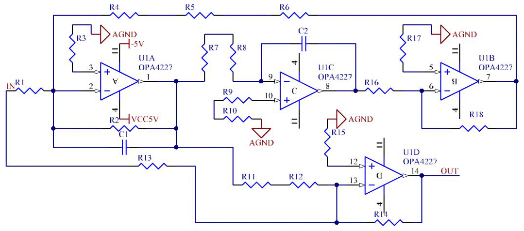
The hardware circuit of the acquisition station is composed of an analog board and a main control board. The analog board is mainly used for signal acquisition, conditioning, and high-precision analog-to-digital conversion. The main control board achieves the control of each unit in the analog board as well as data encoding and transmission. Figure 3 shows a block diagram of the analog board, which has two data acquisition channels for simultaneous acquisition of seismic and electrical data. The analog board uses the AD780 ultrahigh-precision reference voltage source to generate a 2.5 V calibration signal, which is used to perform a self-test on the acquisition channels. An ADG419 chip is used as the analog switch that selects either the detector signal or the calibration signal to enter the low-pass filter circuit, after which the programmable-gain instrumentation amplifier, AD8253, performs program-controlled amplification of the signal. The signal then enters a drive circuit, THS4521, to be converted into a differential signal that finally undergoes high-precision analog-to-digital conversion in ADS1271. Design of the electrical channel is similar to that of the seismic channel. The difference is that an LT1168 precision instrumentation amplifier is used to pre-amplify the signal in the amplifier circuit. Simultaneously, to reduce the interference due to the 50 Hz utility frequency, four operational amplifiers, OPA4227, are used to build the filter circuit, as shown in Fig. 4. The principle behind this is to construct a band-pass filter by using three operational amplifiers and subtract the signal through the band-pass filter from that of the all-pass circuit using the fourth operational amplifier to achieve filtering of the 50 Hz utility frequency signal. Another difference between seismic and electrical channels is the low-pass filter (LPF) parameter. In the seismic channel, the cutoff frequency of the passive LPF is 1.2 kHz and the cutoff frequency of the active LPF in the electrical channel is 3.4 kHz.
The voltage of the power station continuously reduces as it supplies power to multiple acquisition stations in a PoE-like manner, and as a result the voltage entering the acquisition stations varies from 22 to 48 V (determined by the position of each acquisition station). Since the voltages required for the analog board are ±5 V and 3.3 V, a PWB4812MD DC-DC chip is used to first convert the input voltage to 12 V, then a TMR3-1221WI conversion chip and PTH08080W switched-mode power supply are used to convert 12 V to ±5 and 3.3 V, respectively.
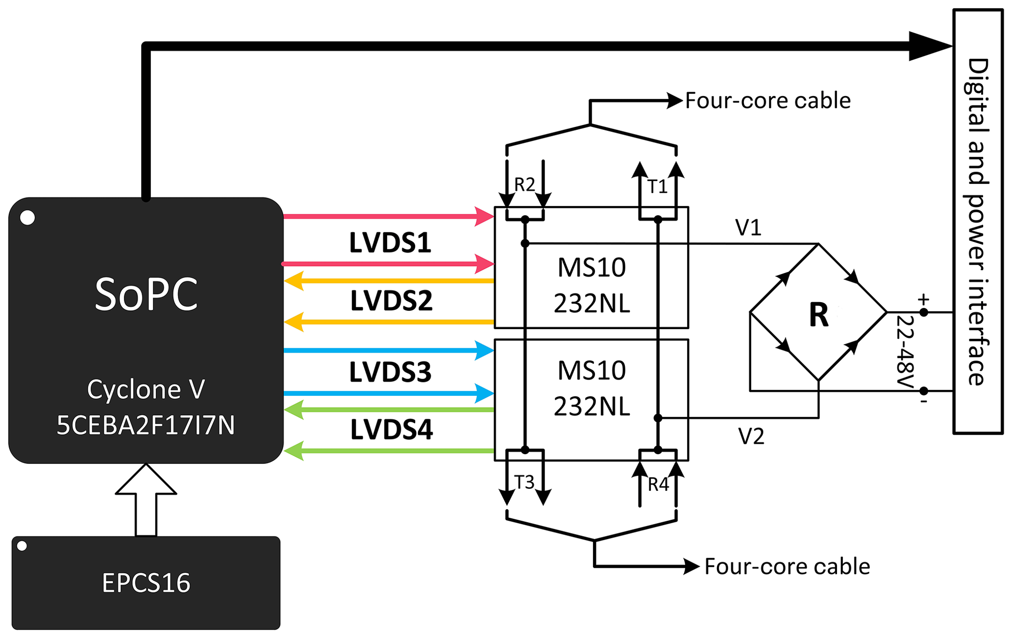
The main control board of the acquisition station is primarily composed of the SoPC, 5CEBA2F17I7N, and its configuration chip, EPCS16. Figure 5 shows a block diagram of the main control data transmission board. The 5CEBA2F17I7N chip is a Cyclone V series FPGA, whose total power consumption compared with the previous generation has dropped by 40 % due to the 28 nm low-power process technology. The main control board uses four pairs of LVDS differential pins on the SoPC and two network isolation transformers, MS10232NL, for data transmission. The advantages of using differential signaling include low power consumption, low bit error rate, low crosstalk, and low noise. (R2, T1) and (R4, T3) are two pairs of transceivers, while V1 and V2 are two lines with a common-mode voltage that are trapped between (R2, T3) and (T1, R4), respectively. The difference in value between the two is recognized by the bridge rectifier circuit, R, as a positive or negative voltage and then transmitted to the analog board for voltage conversion. The digital and power interfaces are used for communication and power supply between the main control board and the analog board.
3.2 Research on the dedicated data transmission protocol of the data acquisition station
An isolation transformer is introduced during LVDS data transmission, which will block the DC component of the signal. As a result, when 0 or 1 appears continuously in the data, the transformer will cause the voltage at the receiving end to drop, leading to the generation of jitters and bit errors in the signal. To solve this problem, this study uses the Manchester encoding technique which represents 0 and 1 based on voltage transitions. Manchester encoding makes it easier to extract a synchronized clock from the signal, and at the receiving end it constantly aligns the valid edges using a method for oversampling. This can reduce the hardware circuit design, as well as the system power consumption, and simultaneously avoid the problem of burrs along the data transition edges.
The encoding module at the transmitting end first converts the 8-bit parallel data in units of bytes into a bit stream output by bit and then transmits the encoded serial data in which “01” is used to represent the binary “0” and “10” is used to represent the binary “1”. The data transmission rate on the transmission line is 16.384 Mbps during the process, meaning that the required encoding clock should be 32.768 MHz. At the receiving end, to detect effective transitions in the Manchester encoded data stream and extract the synchronous clock, a method for oversampling is adopted. The sampling clock frequency used by the decoding module is 8 times that of the data transmission rate, and data sampling, decoding, and shift and byte synchronization are carried out. Through this method of encoding and/or decoding, serial binary data transmission is achieved in the true sense that is enabled only by solving the problems of byte synchronization and frame synchronization. When the receiving end starts to receive one frame of data after receiving the preamble, it first receives the frame header that contains information on the data length of this frame, it then receives data according to the length defined in the frame header, and finally restores this data to parallel data (in bytes).
Based on the characteristics of seismic and electrical data acquisition, a custom data frame was designed to be divided into 51 units, consisting of 816 bytes in total. The first unit is the frame header, and the remaining 50 units are data units for communication between power stations and acquisition stations, as well as between power stations themselves. The data unit follows a specific format, as shown in Table 1, which is arranged in an order from low byte to high byte, starting with the unit header, command, status information, sampled data, and cyclic redundancy check (CRC), and it consists of 16 bytes in total. Within the data unit, sampled data occupies 12 bytes (or four data in total) and the remaining parts each occupy 1 byte.

Data in the acquisition station can be transmitted in two modes: synchronous transmission and asynchronous transmission. As shown in Fig. 6, the asynchronous transmission mode is adopted when reporting status information and uploading data from the slave power station to the master power station, while synchronous transmission mode is adopted when uploading data and status information from the acquisition station to the slave power station or the master power station, as well as when receiving control commands from the master power station (Li, 2018). During synchronous acquisition, the master power station sends out empty data frames. Each acquisition station then decodes these empty data frames, translates them to their corresponding unit, writes the data in the FIFO to the corresponding position of this unit, then sets the unit status byte to 1 and command byte to 0x0F, and finally recalculates the CRC for this unit. In asynchronous transmission, the received data only need to be re-encoded and sent out without modifying the data frame. Therefore, acquisition stations in asynchronous transmission only undertake the task of data transfer between the power stations.
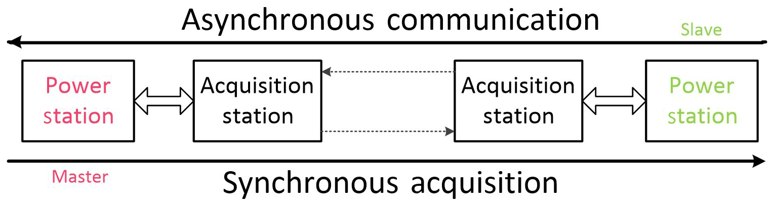
Figure 6Schematic diagram of synchronous data acquisition and asynchronous communication of the data acquisition station.
3.3 High-precision synchronous data acquisition technology
As one of the important indicators to measure instrument performance, synchronization precision determines the quality of the acquired data. Synchronous data acquisition means that all acquisition stations on the acquisition chain collect data simultaneously after receiving the acquisition command. Therefore, eliminating delay in synchronous acquisition commands to reach each acquisition station is a key problem to be solved (Wang et al., 2011; Zhang et al., 2016). Delay in data frame transmission along the acquisition chain can be categorized as follows: delay due to time required on the transmission line, delay due to time spent in acquisition stations in the direction of synchronous transmission, delay due to processing time spent in slave power stations, and delay due to time spent in acquisition stations in the direction of asynchronous transmission. Figure 7 shows the delay of data frames when transmitted back and fourth between the slave power station and the master power station when there are four acquisition stations in between.

Figure 7Schematic of the round-trip transmission delay in data frames between two power stations (MPS, master power station; AS, acquisition station; SPS, slave power station).
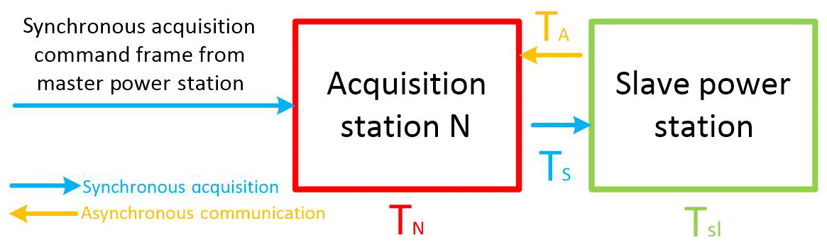
In this study, high-precision synchronization is realized through controlling the acquisition stations by sending synchronous acquisition commands from the master and slave power stations. The master power station sends one frame of data to the acquisition stations (in synchronous acquisition mode) and the acquisition station starts to decode the data frame after receiving it. If a synchronous acquisition command frame is recognized, the acquisition station forwards the data frame to the next acquisition station and starts timing simultaneously. When the same acquisition station receives the synchronous acquisition command frame again (which is returned from the slave power station in asynchronous transmission mode), it stops timing. Hence, if the timed duration at the Nth acquisition station in the acquisition chain is TN, as shown in Fig. 8,
where TA, TS, and Tsl are the time durations required by the synchronous acquisition command frame in the asynchronous transmission process, in the synchronous acquisition process, and in forwarding from the slave power station, respectively. Td is the time difference between synchronous acquisition and asynchronous transmission. Since the time spent transmitting data over cables is the same in both directions for synchronous acquisition and asynchronous transmission, Td can represent the sum of the processing time differences between the two different data transmission modes in the acquisition stations. Assuming that in the jth acquisition station, the time consumed by the synchronous acquisition process is tj and the time consumed by the asynchronous transmission process is – if there are a total of M acquisition stations on an acquisition chain – then
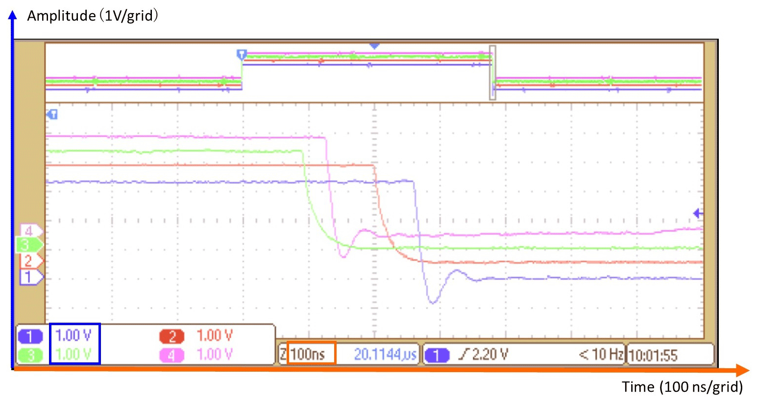
During the data frame transmission process, tj, , and Tsl can be obtained in actual testing. Establishing the same lookup table for each acquisition station allows them to look up their corresponding delay time according to their own location information. In this way, when acquisition stations receive a synchronous acquisition command frame, each of them will delay the corresponding time duration to achieve the purpose of synchronous acquisition. Figure 9 shows the user interface of a four-channel oscilloscope, which is used to observe the synchronous signal outputs from four acquisition stations. After repeated tests and long-term observation, it was confirmed that the synchronous acquisition precision is better than 200 ns, which meets the needs of actual field exploration.
4.1 Equivalent input noise test
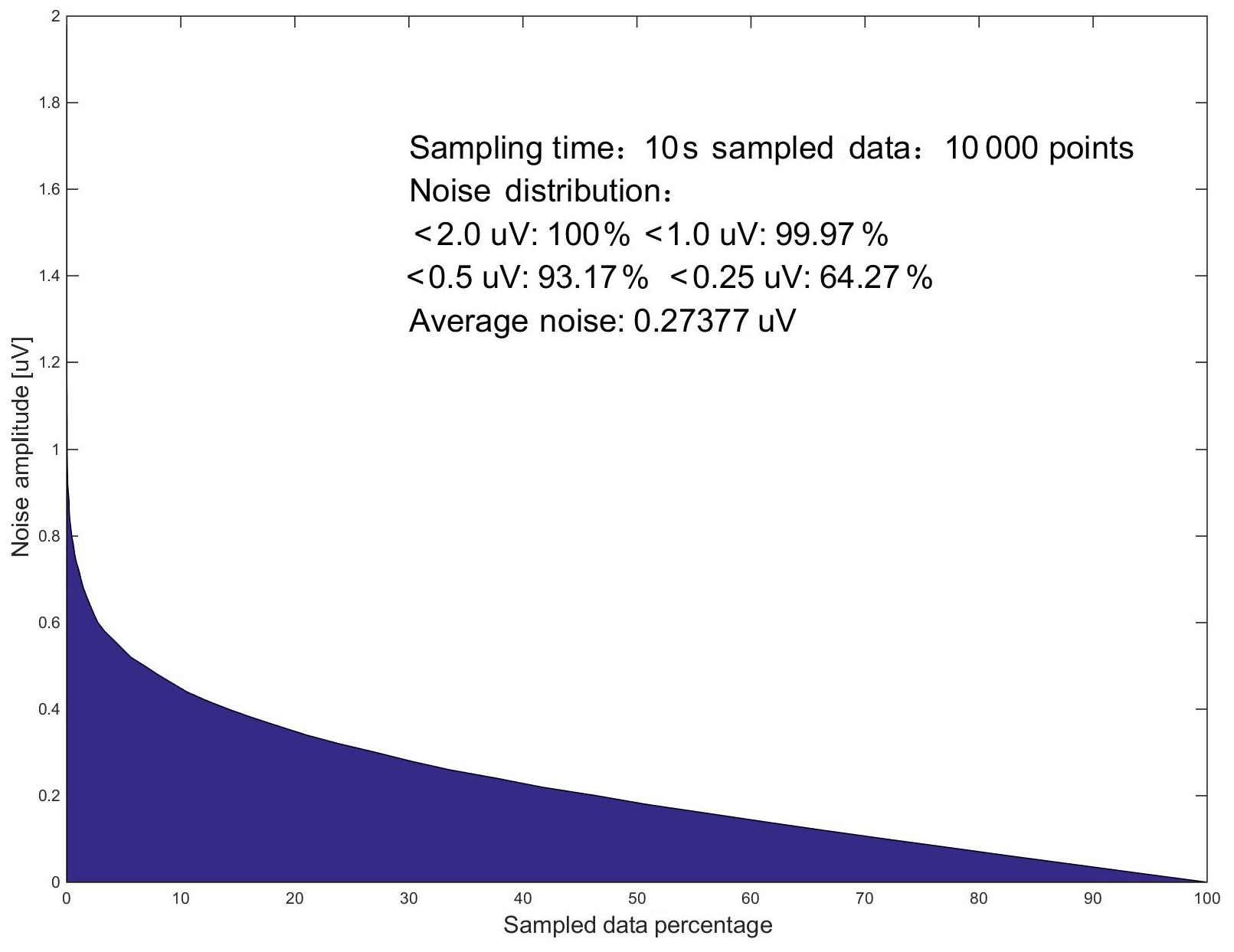
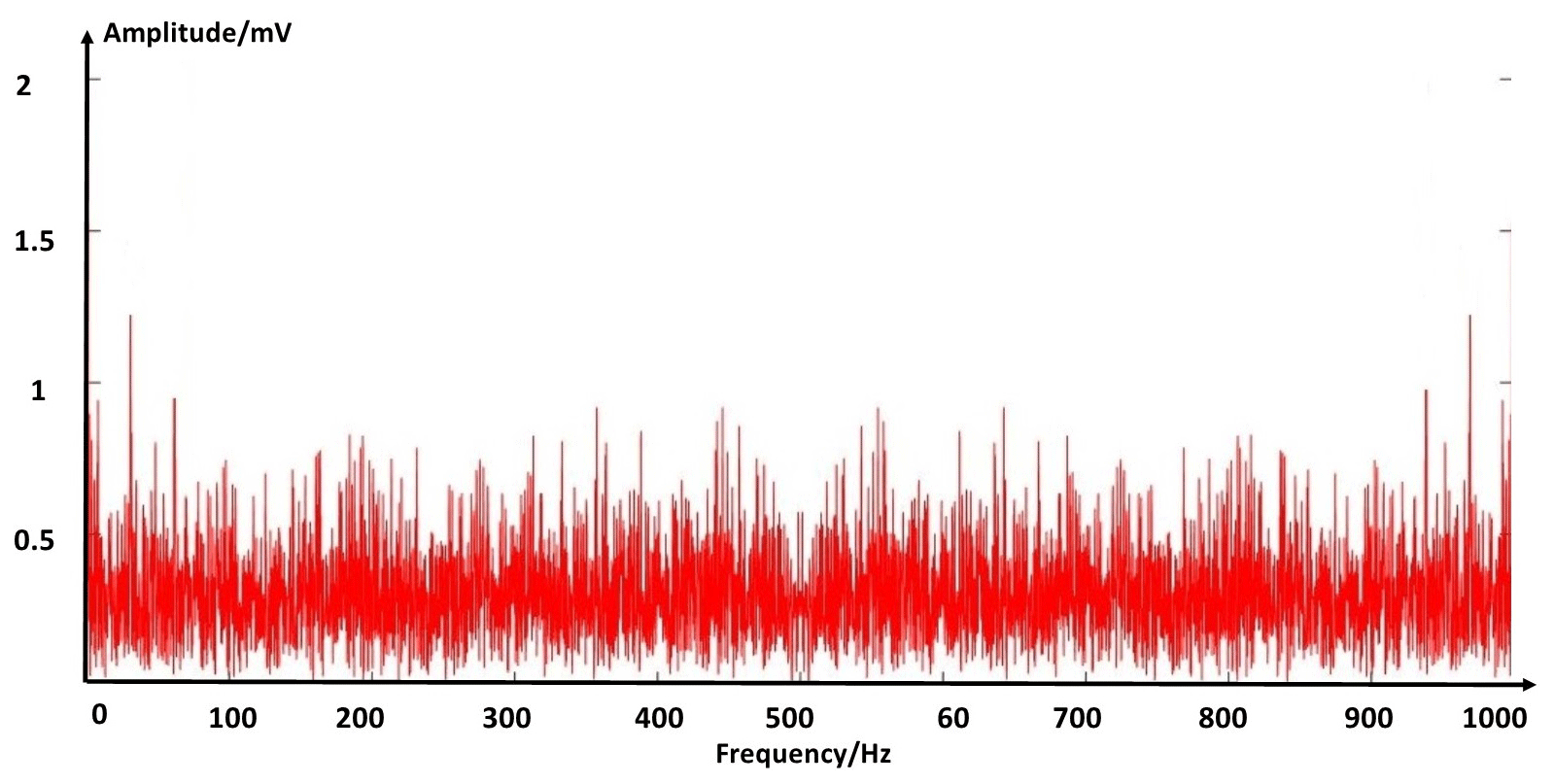
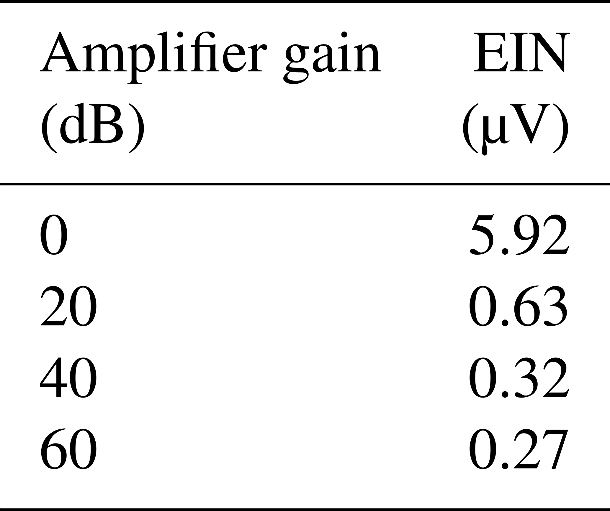
The equivalent input noise (EIN) of the acquisition station, which determines the instrument's ability to resolve weak signals, consisted of a variety of noises. During the test, a 1 kΩ test resistor was connected to the analog-signal input terminal and the sampling rate of ADS1271 was configured as 1000 samples per second. When the front-end gains of both channels were set to 0, 20, 40, and 60 dB, 10 s of data sampling was performed at each station. Furthermore, acquired data were analyzed with MATLAB. Figure 10 shows the distribution of the EIN of a data acquisition station with a sampling rate of 1000 SPS and gain of 60 dB; the noise distribution is similar to Fig. 10 at other gains. Figure 11 shows the spectrum of the equivalent input noise in the 0–1 kHz band when the gain of the acquisition station is 0 dB.
The calculation results of EIN at different gains for the acquisition station are shown in Table 2.
4.2 Channel crosstalk test
Since there are two channels on the analog board, they will inevitably cause mutual interference. During the first test, the electrical channel was short-circuited and a sine wave with a frequency of 31.25 Hz and a peak-to-peak value of 4 V was input into the seismic channel, with the gain set to 1. Data acquisition was performed at different sampling rates and then MATLAB was used to obtain waveform diagrams, as shown in Fig. 12. Then, the seismic channel was short-circuited and a sine wave with a frequency of 1 kHz and a peak-to-peak value of 2.5 V was input into the electrical channel. After performing fast Fourier transform (FFT) processing for the data, it was found that at a frequency of 1 kHz the relative power (8 dB) of the electrical channel is much larger than that of the noise (−128 dB) in the seismic channel in Fig. 13, indicating that the level of crosstalk between the channels satisfies design requirements.

Figure 12Time domain waveform of each channel during the first crosstalk test (red: seismic channel; green: electrical channel).

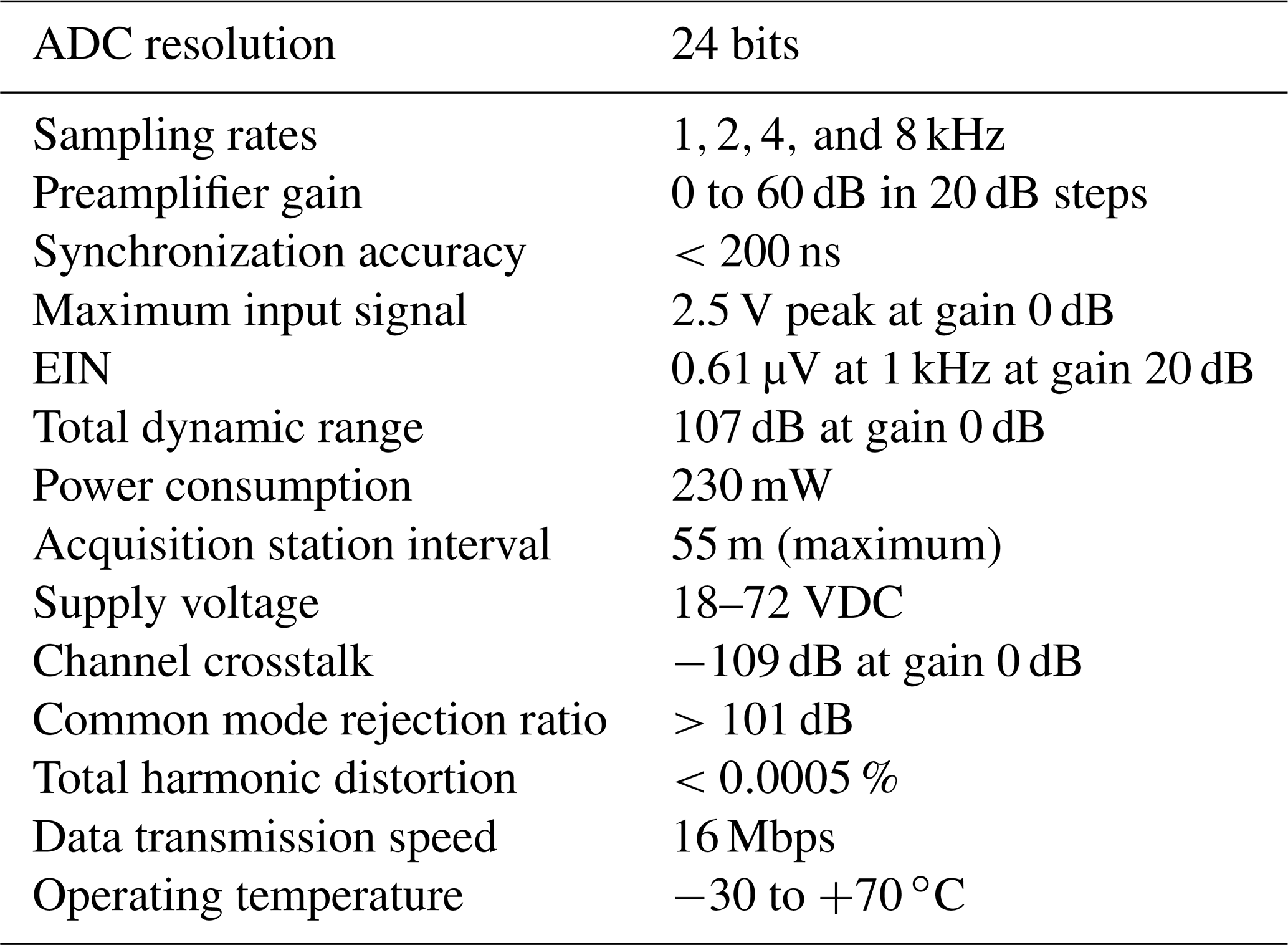
4.3 Summary of performance indicators
Laboratory and field test analyses show that the functions and performance indicators of each channel of the acquisition station developed in this study meet the expected design requirements. The main performance indicators are shown in Table 3.
Based on SoPC technology, this study develops a new type of distributed seismic and electrical hybrid acquisition station. The paper mainly explores the following technical aspects:
-
High-precision integrated seismic and electrical acquisition technology. Different front-end signal conditioning circuits were designed based on the characteristics of seismic and electrical signals and a 24-bit delta-sigma (Δ-Σ) ADC was used to achieve high-precision data acquisition.
-
High-speed low-power data transmission technology. A dedicated data transmission protocol and data frame format were designed. In addition, based on the improved LVDS data transmission technology independently developed, functions of synchronous acquisition and asynchronous transmission were developed according to actual needs to enable low-power data transmission at a speed of 16 Mbps along a 55 m cable.
-
High-precision synchronous acquisition technology. Acquisition stations were controlled by sending synchronous acquisition command frames from both the master and slave power stations with a synchronization precision better than 200 ns.
-
Highly integrated hardware circuits. In addition to signal conditioning and ADC circuits on the analog board, the digital circuits of the acquisition stations and the key technologies were integrated into a single-chip SoPC device for subsequent streaming and upgrade.
The schematic of the 50 Hz filter circuit is available upon request (zqs@cugb.edu.cn).
QisZ and WL developed the required circuits. FG and SQ developed the required software. ZY and QimZ performed the tests.
The authors declare that they have no conflict of interest.
We would like to thank the reviewers for helping us to improve the paper. We would also like to thank Editage (http://www.editage.cn, last access: 14 August 2019) for their English language editing services.
This research has been supported by the Natural Science Foundation of China (grant nos. 41574131 and 41204135), the National “863” Program of China (grant nos. 2012AA061102 and 2012AA09A20102), the National Major Scientific Research Equipment research projects of China (grant no. ZDYZ2012-1-05-01), and the Fundamental Research Funds for the Central Universities of China (grant no. 2652015213) and the China Scholarship Council.
This paper was edited by Valery Korepanov and reviewed by three anonymous referees.
Astarloa, A., Bidarte, U., and Lazaro, J.: Multiprocessor SoPC-Core for FAT volume computation, Microprocess. Microsy., 29, 421–434, 2005.
Chen, K., Jin, S., and Deng, M.: Multifunction waveform generator for EM receiver testing, Geosci. Instrum. Method. Data Syst., 7, 11–19, https://doi.org/10.5194/gi-7-11-2018, 2018.
Chen, R. J., He, Z. X., Qiu, J. T., He, L. F., and Cai, Z. X.: Distributed data acquisition unit based on GPS and ZigBee for electromagnetic exploration, 2010 IEEE Instrumentation and Measurement Technology Conference Proceedings, 2010.
Cheng, S., Deng, M., Wang, M., Jin, S., Zhang, Q., and Chen, K.: A wireless monitoring system for a high-power borehole-ground electromagnetic transmitter, Geosci. Instrum. Method. Data Syst., 8, 13–19, https://doi.org/10.5194/gi-8-13-2019, 2019.
Di, Q. Y., Fang, G. Y., and Zhang, Y. M.: Research of the Surface Electromagnetic Prospecting (SEP) system, Chinese J. Geophys.-Ch., 11, 3629–3639, 2013.
Guo, J., Liu, G. D., Xu, S. H., and Liu, N.: Computer network-based novel digital seismograph with mega-channel level, Ref.No:CN102628957A, Chinese Patent, 2012.
Huang, X. L. and Yu, J. S.: Numerical analysis for the characteristics of SN338 digital seismic instrument, Chinese J. Geophys.-Ch., 37, 597–602, 1994.
Li, S. H.: Research on Data Transmission Technology in Seismic and Electrical Distributed Acquisition Stations, China University of Geosciences (Beijing), Beijing, 3–26, 2018.
Lin, J., Fu, L., Wang, Y. Z., Xu, J., Ji, Y. J., and Yang, M. M.: Development of sensor used for grounded electrical source air-ground transient electromagnetic detection, Journal of Jilin University (Engineering and Technology Edition), 3, 889–894, 2014.
Liu, G. D.: Developing earth exploration technology in three dimension, improving the performance of instrument for geosciences, Chinese J. Geophys.-Ch., 56, 3607–3609, 2013.
Liu, G. D.: Promote the innovation of geophysical methodology, and lead the future of exploration apparatus technology, Chinese J. Geophys.-Ch., 60, 4145–4148, 2017.
Mrmureanu, A., Ionescu, C., and Cioflan, C. O.: Advanced real-time acquisition of the Vrancea earthquake early warning system, Soil Dyn. Earthq. Eng., 31, 163–169, 2011.
Qiao, S., Duan, H., Zhang, Q., Zhang, Q., Li, S., Liu, S., Liu, S., Wang, Y., Yan, S., Li, W., and Guo, F.: Development of high-precision distributed wireless microseismic acquisition stations, Geosci. Instrum. Method. Data Syst., 7, 253–263, https://doi.org/10.5194/gi-7-253-2018, 2018.
Van, D., Spitzer, R., and Green, A.: Design and application of a towed land-streamer system for cost-effective 2-D and pseudo-3-D shallow seismic data acquisition, Geophysics, 66, 482–500, 2001.
Wang, H. S.: Key Problem Research on Data Transmission of Large-scale Seismic Acquisition and Recording System, PhD thesis, Tsinghua University, Beijing, 40–62, 2010.
Wang, Q., Deng, M., and Zhang, Q. S.: High-Precision synchronous implementation during seismic data acquisition, Adv. Mat. Res., 171-172, 764–768, 2011.
Zhang, L. H.: Study on Data Transmission Techniques Based on Relay Ethernet in Seismic Exploration Using Vibroseis, PhD thesis, Jilin University, Jilin, 30–50, 2007.
Zhang, Q. S., Deng, M., Yang, K. P., Chen, K., Wang, M., and Sun, Z. C.: Application of SoPC on High-precision Geoelectric Data Acquisition System, Geoscience, 26, 1306–1311, 2012.
Zhang, Q. S., Deng, M., Guo, J., Luo, W. B., and Wang, Q.: Development of a new seismic-data acquisition station based on system-on-a-programmable-chip technology. Ann. Geophys., 56, 1–9, https://doi.org/10.4401/ag-6309, 2013.
Zhang, Q. S., Jiang, J. J., Zhai, J. H., Zhang, X. Y., Yuan, Y. J., and Huang, X. W.: Seismic Random Noise Attenuation Using Modified Wavelet Thresholding. Ann. Geophys., 59, 1–10, https://doi.org/10.4401/ag-7097, 2016.
Zhang, X., Zhang, Q., Wang, M., Kong, Q., Zhang, S., He, R., Liu, S., Li, S., and Yuan, Z.: Development of a full-waveform voltage and current recording device for multichannel transient electromagnetic transmitters, Geosci. Instrum. Method. Data Syst., 6, 495–503, https://doi.org/10.5194/gi-6-495-2017, 2017.
- Abstract
- Introduction
- System-on-a-programmable-chip technology and distributed telemetry data acquisition system
- Key technologies of the new distributed hybrid seismic and electrical data acquisition station
- Summary of acquisition station test and performance
- Conclusions
- Data availability
- Author contributions
- Competing interests
- Acknowledgements
- Financial support
- Review statement
- References